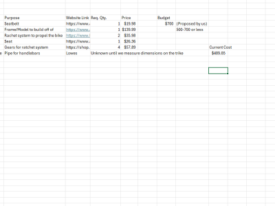
Our team has been given the task of designing an entertaining rowing bike for young students that have conditions preventing them from using traditional bikes.
Many young students all around the world struggle with physical and mental blocks that prevent them from using a traditional pedaling bike. Recently, we were notified of the need that local students have for an alternative way to ride. While they may not have the ability to partake in this essential activity, it is important they have access to another way. After discussing certain design parameters and specific needs with our POC, Mrs. Draper, our challenge became clear. We needed to create a bike that gives these students a similar way to enjoy the ride and reap the physical benefits of a bike.
Main Specs:
Side Specs:
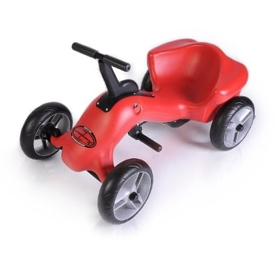
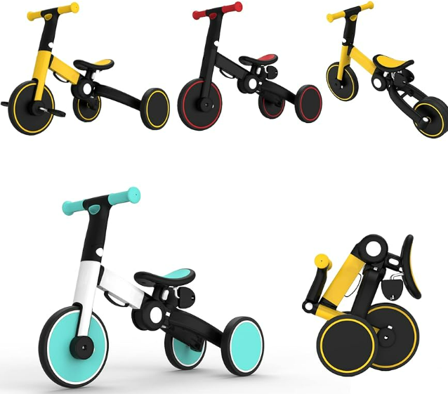
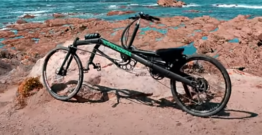
We first started off with are research by coming together as a group and reviewing some designs that have already been created. We viewed the last project to see where there research took them and found it to be helpful in how the bike should look, being its dimensions and overall size. We found that their way of making the bike safer, they deamed it as the sandwich method, was a great starting point to cover up the inside workings of the bike. We then started our own search. It started off very specific, small kid trikes that use the front rowing motion to propel the user forward. This is shown in our red Pumper Trike example. This design was sent to us by Mrs. Draper, our POC for the entirety of our project. This same bike was used as a template for previous groups before us. It acts as a baseline and a safe choice when it comes to non-pedaling bikes. We then expanded our search into more designs that could offer possible different approaches and designs that we can incorporate into our design specs. The mobility and simplicity of the basic trike (blue and yellow) offers some base concepts that can be used to aid the weight aspect and great mobility to be used in our design. Some of the more complex designs like the propelling motion and turning part of the bike can be taken off of the RoadRower (black and green). This is a “adult” version of our vision. While we will make a more simplistic version of it, this can aid us in how we will construct our bike. This baseline research will allow us to continue creating our design and aid us in our design specs.
This design follows off of the basis for last years design. It has the “sandwich” protective piece they designed while also being a little lower to the ground. Some of the main differences are the pedals in the front of the trike instead of at the bottom of the trike. We found that having them on the ground might make it a little harder for the students to push off of while propelling the trike forward. Pushing the pedals out allow for the user to have an easier, more natural stance on the bike, improving the form while riding and reducing the risk of back muscle injuries. The bike would be moved forward by a simple gear design on the pulling motion of the handle bar. This handle bar is at chest/shoulder level, allowing for the users to get as much torque on the gear system as possible, all the way through the motion. This allows for a speed that is comfortable for guardians that will be with the student, and a speed that is fun for the user. The turning system still needs to be discussed, possible brakes can be put onto the back wheel in which the user can squeeze an extension of the side of the handle bar that correlates to the side they want to turn. The squeezing motion brakes the correlating back wheel, turning the bike in the direction they want to go.

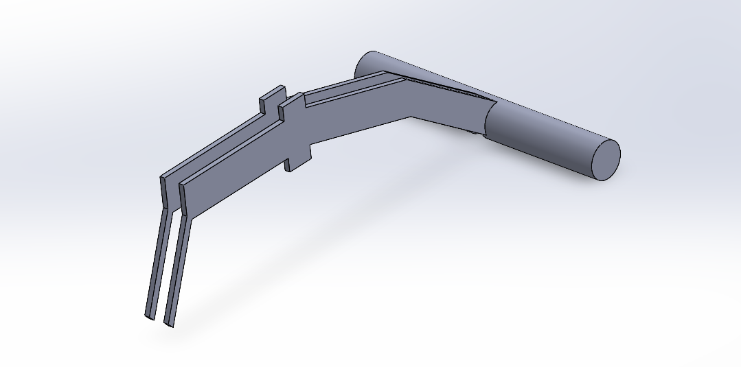
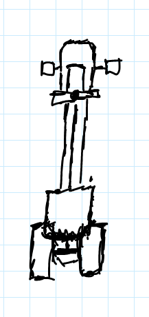
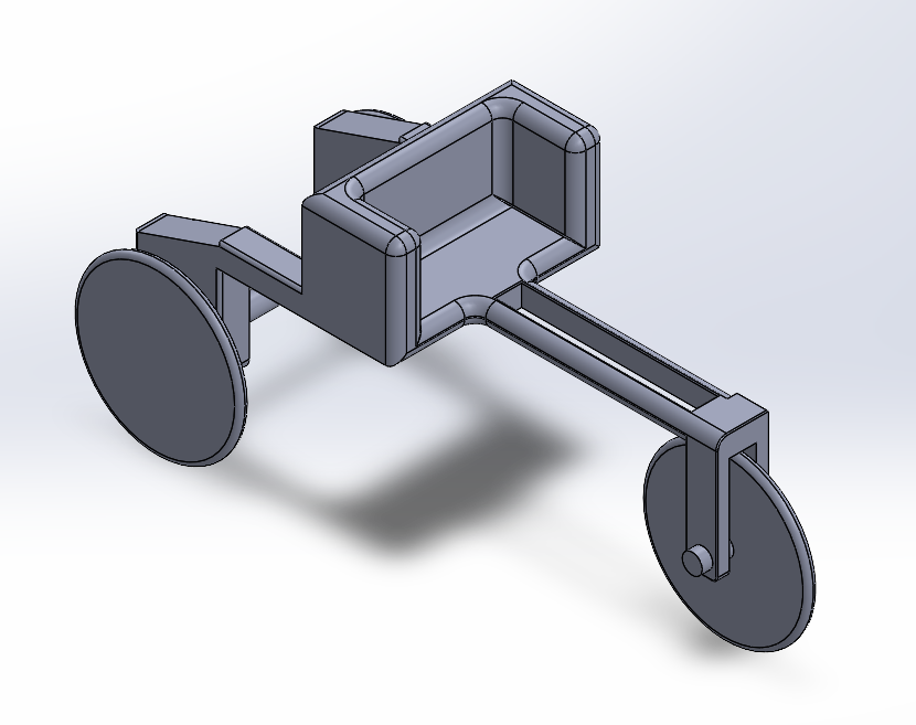
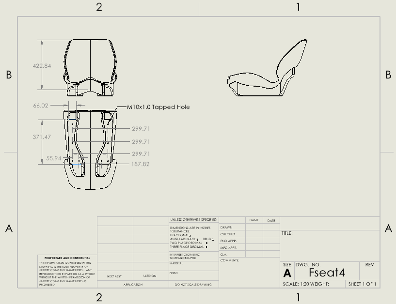
This is a design for the main body (modeled in solidworks) that excludes the moving pieces. One of the specific points brought up in discussion was the necessity for a “bucket seat”. The purpose of the seat is to help kids balance on the bike more easily while accommodating kids of different sizes and weights. Another point brought up was balance. The bike design should be stable and not easily flipped. A wider base on the back two wheels will go a long way in preventing the bike from toppling.
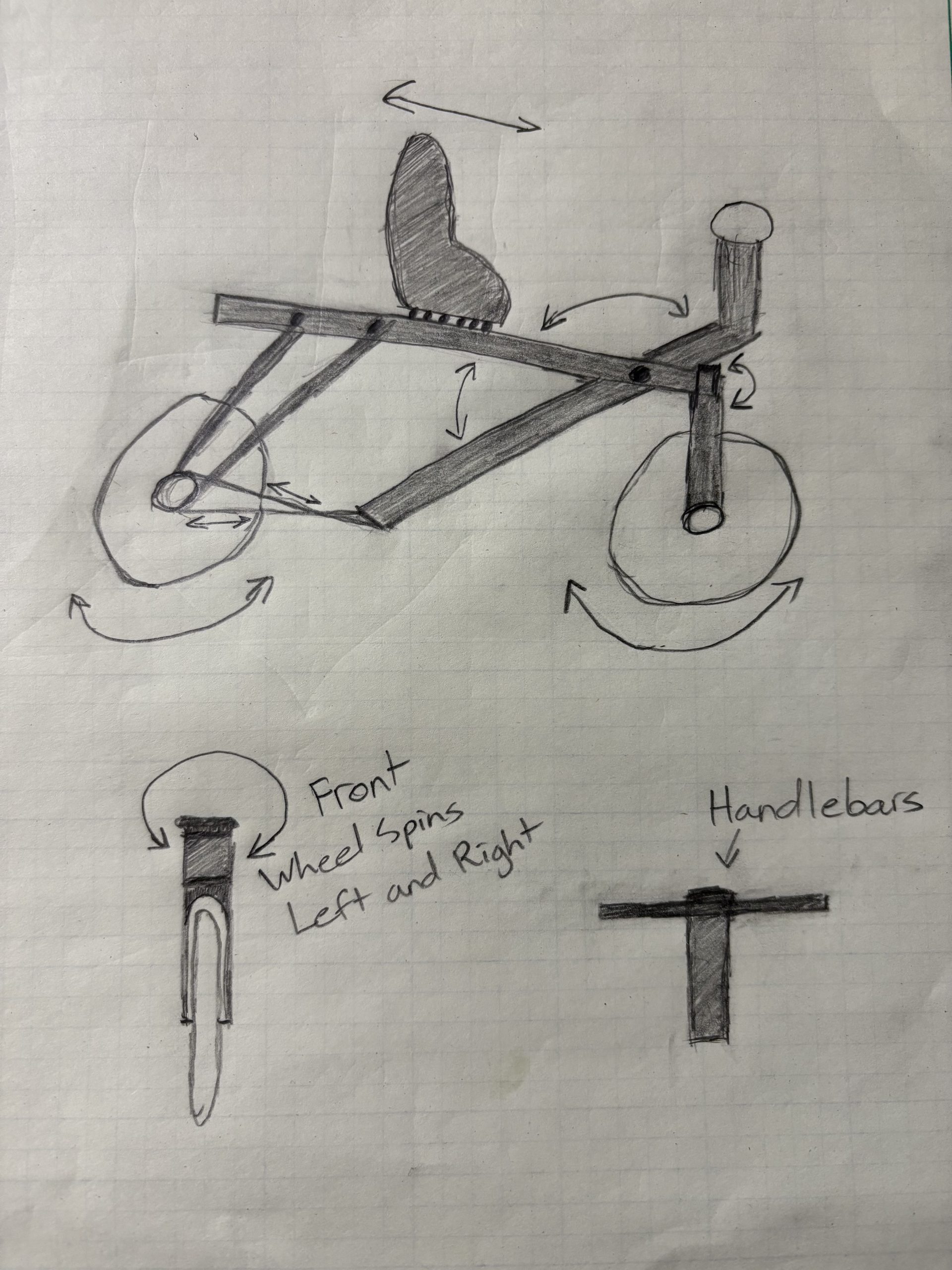
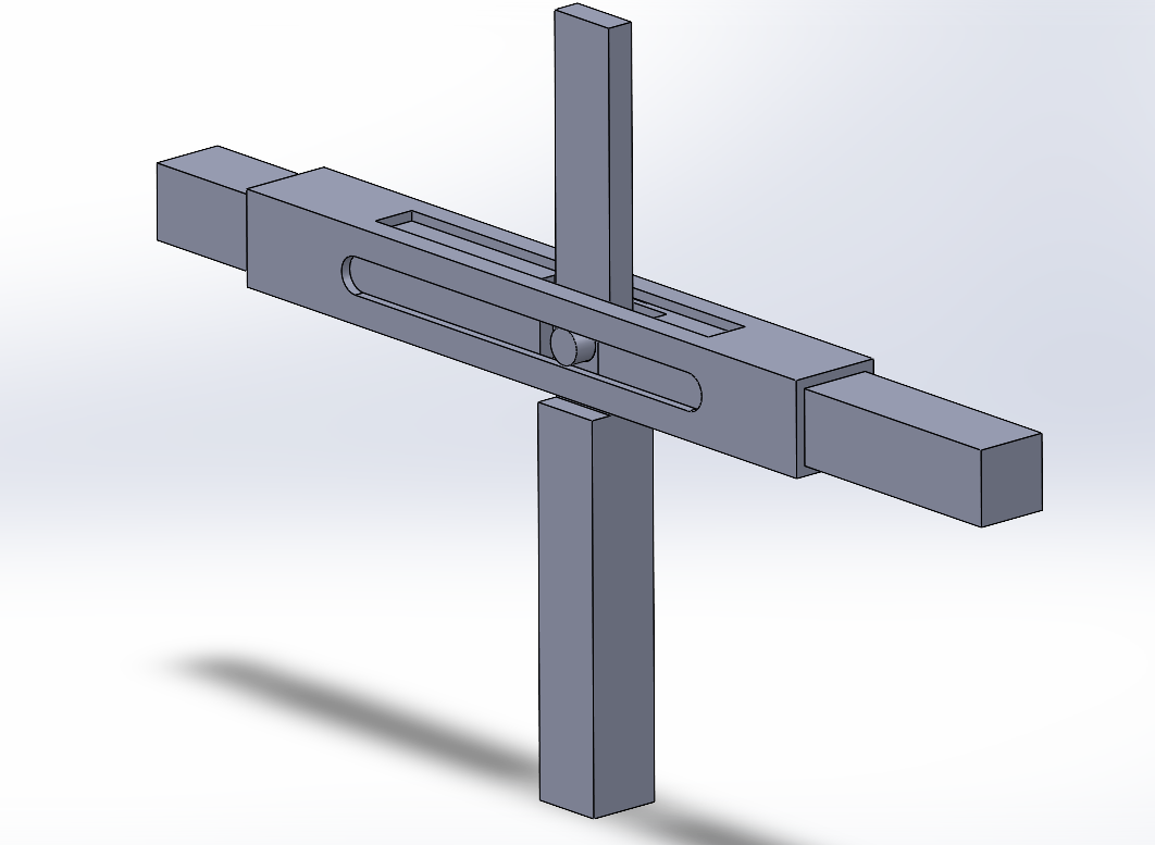
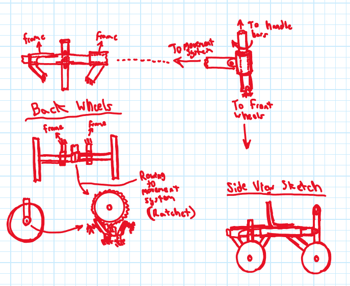
This design was derived from demand of the push and pull, and ease of steering ideas listed in the design specifications. The focus is on the method of changing translational motion into rotational motion. The concept design features a “ratchet-like” system that would allow the rotation to be directly controlled by the rider. Using a design similar to a ratchet would allow movement both forward and backward.
The back two wheels are connected to each other by an axle. The center of the axle will contain the ratchet system. The gear teeth would be fastened to the axle allowing the ratchet bar to rotate around it. The ratchet bar is connected to the beam that is moved by the push and pull of the handlebars. This beam is encased by a hollowed rectangular beam. The ratchet bar and the moving beam are connected by a bolt, allowing the ratchet bar to rotate around the axle while the beam is moving along a single axis.
The handlebars would be connected, by a round bar, to a small cylinder in the center of the front axle. This would allow the handlebars to move without impeding the movement of the front axle. A small cylinder with a hinge is placed around the round bar and connected to the rectangular beam. This ties the movement of the handlebars to the movement of the ratchet bar.
The frame is built around the rectangular beam casing. It would connect to the back axle with bearings and potentially the same with the front. The seat would sit on the beam casing and would have the ability to translate along the beam for desired comfort.
The steering in this design presents a challenge. For the bike to stand on its wheels, both axles will need to be connected to the frame since the handlebars aren’t directly connected to the beam casing. Fixing the axle to the frame will make any form of rotation around the round bar unobtainable. A solution for this issue could be achieved by making a separate mechanism for the rotation of the front wheels. It could either be dependent on the position of the handlebars or feet pedals could be used to determine the direction.
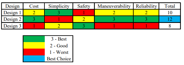
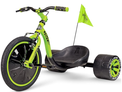
We ended up choosing a design that combined all of our models together with a little twist. We incorporated the design and turnability of the Razer Trike. A drifting trike type vehicle that we could modify to fit the needs of the students.
Our selected concept design incorporates all of our concept designs while also integrating a new base trike. We decided to use the Razer Trike model as a base that we can modify off of. This helps us know that the trike will be able to hold all shapes and sizes, while also carrying the weight of heavier passengers. One of the problems our POC faced last year was that the kids would easily break the product just by sitting on it and cranking on the pumper mechanism. This base allows us to account for it while also leaving it open to any further modifications.
We modified the already made Razer Trike. We found the rough idea of the trike in a SolidWorks part library and started from there. We combined our earlier design thoughts in order to find a way that we can both still have this bike turn and be fun for the students with drifting motion, while also being pump propelled. These combined ideas led us to our final design, roughly shown in the CAD model.
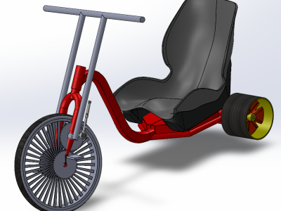
We first ripped out the handlebars and made new ones that would allow for the intended pumping motion. These handlebars would connect down to a series of gears that would propel the bike forward. These handlebars also offer the ability to turn. While limited these will help to start the initial turning motion, that can later be turned into a drifting motion. They need to be strong, so a thick steel/alloy steel will be used to create these bars. This along with welding will help to create bars that won’t break on the user.
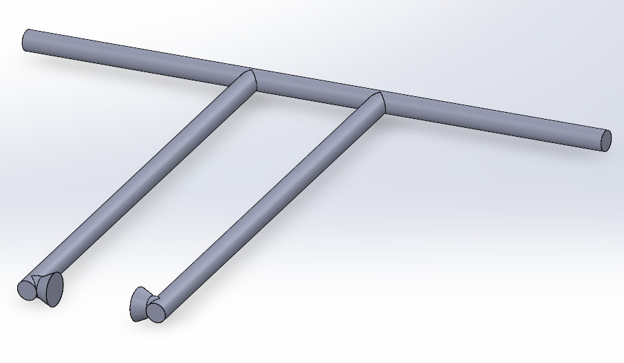
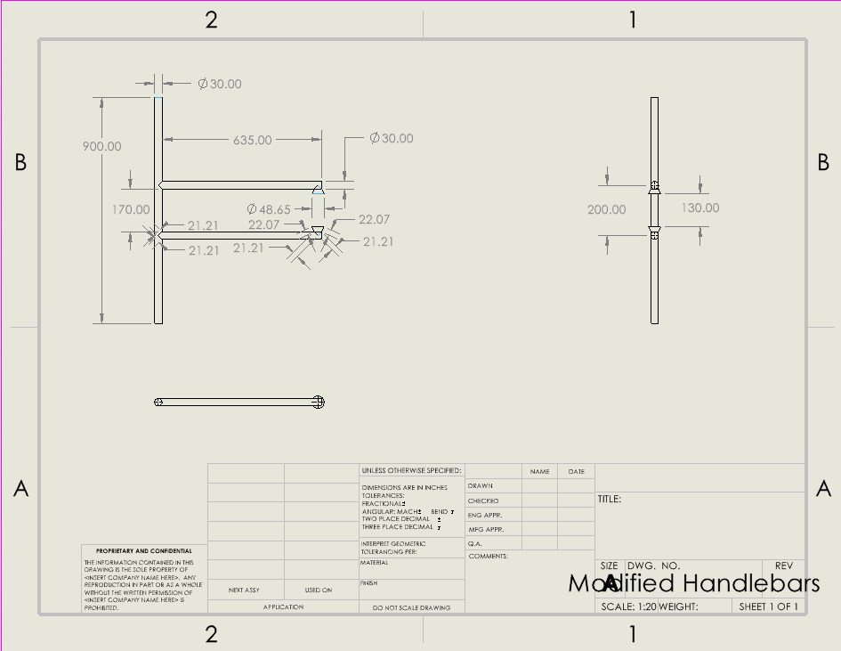
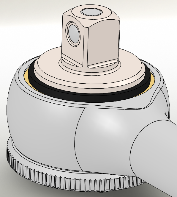
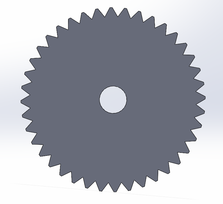
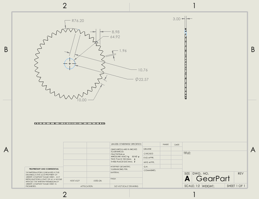
We then set our sights on how we were going to approach the propelling system. We decided on 2 gears in series on each side. One would be the receiver of the pulling motion and start the gears spinning. The second gear would be grouped in series with the first one, receiving the spin and reversing the direction, in turn spinning the tire in the forward direction. This gear system of course would be thicker, in order to prevent it from being broken easily. The gear system would be covered up by a 3D printed piece that can be removed in case something needs to be fixed. This would prevent the rider from accidentally being hurt from this system. In order to stop the pushing motion on the bar from reversing the direction, we will add a torque wrench type action that way the bars can reset and be ready to be pulled again. The gear design shown doesn’t fit our criteria for durability and will therefore be changed to be thicker upon starting construction.
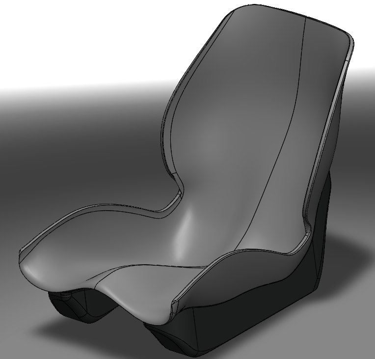
Our final implementations to this design is the bigger bucket style seat for comfortability, an added seatbelt to keep riders in tight, and to remove the ability of the pedals to move the bike forward. The pedals will now instead have straps around them, and a damper type function, this way the rider can still pedal and the dampers will give the rider a light leg workout if they choose too. The pedals themselves will be reused from the bought original design, and we will rip out the current seat and bolt down the seat we will obtain. Holes will be cut into the seat to allow a simple belt loop to be put through with a locking and tightening function.
Day 1:
We began the fabrication process by assembling the bike we ordered. This allowed us to view how the bike fork connected to the chassis and gave insight as to how the wheel’s internal sprocket would perform. After assembly, we tested the bike’s wheel to ensure that the sprocket functioned as anticipated. This feature is what would allow the push motion to rotate the wheel. After verifying, we took the pedal adapter on one side and matched it to the other.
Day 2:
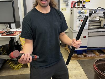
We started by finding lever bars that would properly fit around the pedal adapters. Luckily, we found two pipes that were perfect for what we needed. Wider at the top while being smaller at the connection point. Since we knew that the pipes were going to be welded, we grinded/sanded the paint off of the welding point. Afterwards, we removed the handlebars and slid the pipes onto the pedal adapters. We then tested the performance with everything loosely attached. We found that the bike was not fast and that the sprocket engaged late in response to the user’s movement. This meant we needed to find a method that would compensate for these flaws.
Day 3:
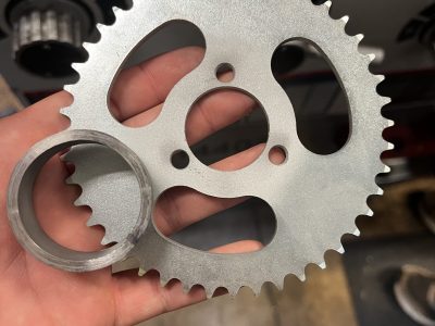
While we intended to build a bike that utilized push and pull movements, we were unable to find a feasible design. Therefore, we decided on relying on a push motion to move the bike. This would allow the use of gears and chains. The gear ratios, in theory, would compensate for the sprocket’s late engagement and increase the bike’s speed. With this idea in mind, we started mapping out how we would attach the small gears to the axle, and how we would attach the large gears to the fork.
Day 4:
We decided on attaching the small gear directly to the axle where the pedal adapters were previously attached. Since the levers were going to be attached to the upper gears, this left the perfect spot for the small gears. We decided on attaching the bigger gears to the fork using rounds peg and bearings. For this method to work, we needed to…
All of these needed to be achieved while also ensuring that the mechanisms can be secured to the fork. We started by making the housing unit for the bearing. To make sure everything lined up, we made an adapter piece that fit into the center of the gear while retaining the same diameter as the inside of the housing unit. This ensured that the pieces were centered when we welded them together.
Day 5:
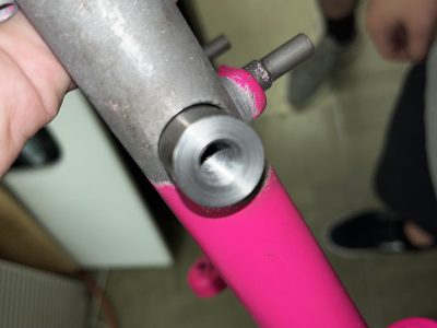
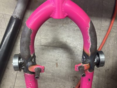
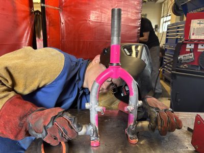
We started the day by cutting two small cylinders that we used as pegs. These pegs were a perfect fit for the bearings we chose. We initially rough cut these pieces to determine the best length. The pegs needed to go through the fork pipe for extra stability. After ensuring that we could fit the pegs through the fork while also being able to hold the gear, we drilled two holes into the fork. These holes needed to be the exact same on both sides, so we used the milling machine to make the best estimation. After ensuring the peg could fit through the holes, we cut down the length using a lathe. Afterwards, we threaded a hole into the center of each peg. This is how we secured the gears and bearings onto the fork.
Day 6:
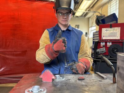
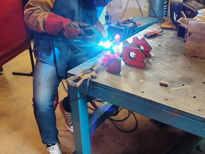
We started by welding the pegs onto the fork. To ensure durability, we welded the pegs on both sides of the holes. Since the welds left rough and protruding bubbles, we needed to grind them down. This would allow the bearing to fit on the peg like it was supposed to.
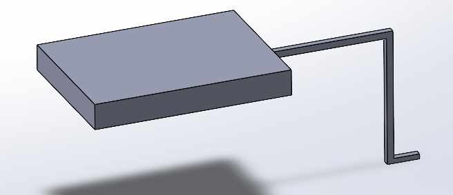
While the fork was being worked on, we simultaneously began working on attaching our new, more comfortable bucket seat to the chassis. Since the mounting plate was too small for the seat, we needed to create an adapter piece that would connect to the plate to the seat.
Day 7:
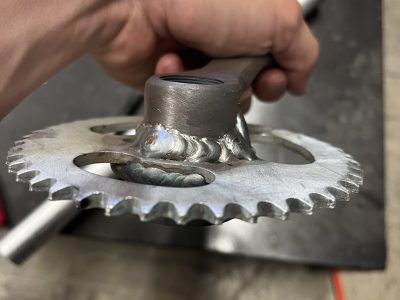
We started the day by welding the pedal adapters onto the large gear. The challenge with this process was ensuring that the gear face and the adapter were parallel with each other. We welded the adapter straight onto the gear, opposite of the bearing side. After allowing the welds to cool, we loosely assembled the mechanism. Using the distance between the gears as reference, we shortened our purchased bike chains. We made sure that the chains had little to no slack in order to eliminate any issues with controlling the motion.
We also secured the small gear onto the wheel’s axle. We simply put a bolt through the center of the gear and screwed it into the axle. To ensure tightness, we used Loctite in the hole and on the gear where it was touching the axle and the bolt head. After doing it to both sides, and letting the fastener settle, the gears felt solid.
Day 8:
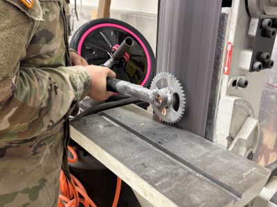
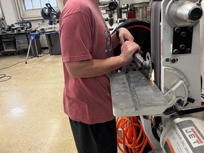
The objective for the day was to attach the levers to the gears by welding them onto the pedal adapters. In order for the welds to actually stick to the material, we had to cut into the pipe so it could wrap around the adapter. We used an electric grinder with a cutting wheel to cut straight vertical and horizontal lines into both levers. Afterwards, we put the levers onto the adapters and used a bench vice to mold them to the same shape. We were then able to weld the pieces together with minor inconsistencies. After the welds cooled, we noticed the gears were not rotating straight and in line with the bottom gears. We then used a vertical grinder to sand down the bearing housing. This made the gear rotate smoother and in line. We then welded foot pegs to the fork with some leftover pipe. We then put the bearings onto the pegs, we put the chain around both gears, then slid the top gear onto the bearing. This ensured the chain stayed taught. We then put a flat washer on pedal adapter then screwed a bolt through to the peg. This held everything together.
Day 9:
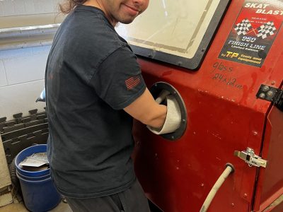
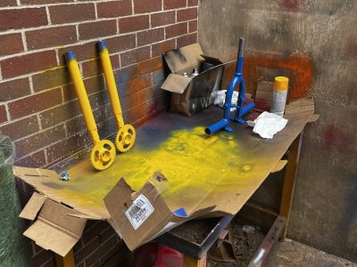
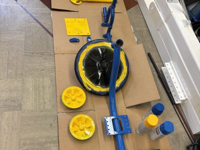
After making sure the device worked, we disassembled everything and started painting. We chose a blue and yellow color scheme. We left the edges of the levers unpainted in order to attach handlebars.
Day 10:
Once everything was dry, we assembled all of the parts. We made sure to keep the levers in the same place to make sure the handlebars lined up correctly. We used the electric grinder to make notches in the levers to make welding possible. We then welded the handlebars onto the levers. After cooling, we added a paint coating and touched up any scrapes. Once dry, we applied tape to the handlebars for a grip. We then secured the bike pedals to a pipe that slid into the foot pegs. These pedals had velcro straps that will keep the feet planted and improve turning efficiency. We then secured the fork to the chassis using the given bike equipment and concluded the design process.
![Image[5]](https://techengineeringforkids.com/wp-content/uploads/elementor/thumbs/Image5-scaled-r574ukuza35a93pfn14ftpdhappvbygbz091wxe1fc.jpeg)
![Image[4]](https://techengineeringforkids.com/wp-content/uploads/elementor/thumbs/Image4-scaled-r574uea3y8w9ztyzpga1u91950mau2q7m3onjznsmw.jpeg)
![Image[2]](https://techengineeringforkids.com/wp-content/uploads/elementor/thumbs/Image2-scaled-r574u06j3qcz5ojgzs6naulc88jsmm68k5wdcu8p88.jpeg)
![Image[1]](https://techengineeringforkids.com/wp-content/uploads/elementor/thumbs/Image1-r574tujhyq5980rnwpqvvw0knxblcfjujdzgh6h29k.jpeg)
![Image[3]](https://techengineeringforkids.com/wp-content/uploads/elementor/thumbs/Image3-scaled-r574u8n2t8ok2676mduafaghkpe3jw3tlbrqobw5o8.jpeg)
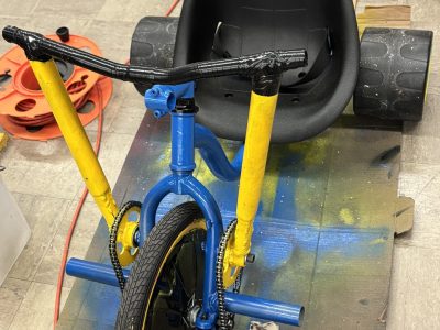
We went to show Dr. Canfield our completed bike design and get it approved. Before this we each took turns sitting in the bike and making sure that it could support our full weight and function properly. We were able to all use the bike with our full weight (200+ lbs) and it worked as planned. While Dr. Canfield tried out the bike he seemed to enjoy the ride and had a few quick improvements that we added. We also had our Heat Transfer teacher Professor Farhat try it out. She is the smallest that went on the bike and was able to use it pretty well. The only thing we had to note was the little difficulty in getting the bike started, but once it is started it goes quick. Our improvements afterward were to tighten everything down, replace the ball bearings in the top, and to cover the ends of the handlebar pipes with a smooth edge in order to ensure they wouldn’t cut themselves while using it.

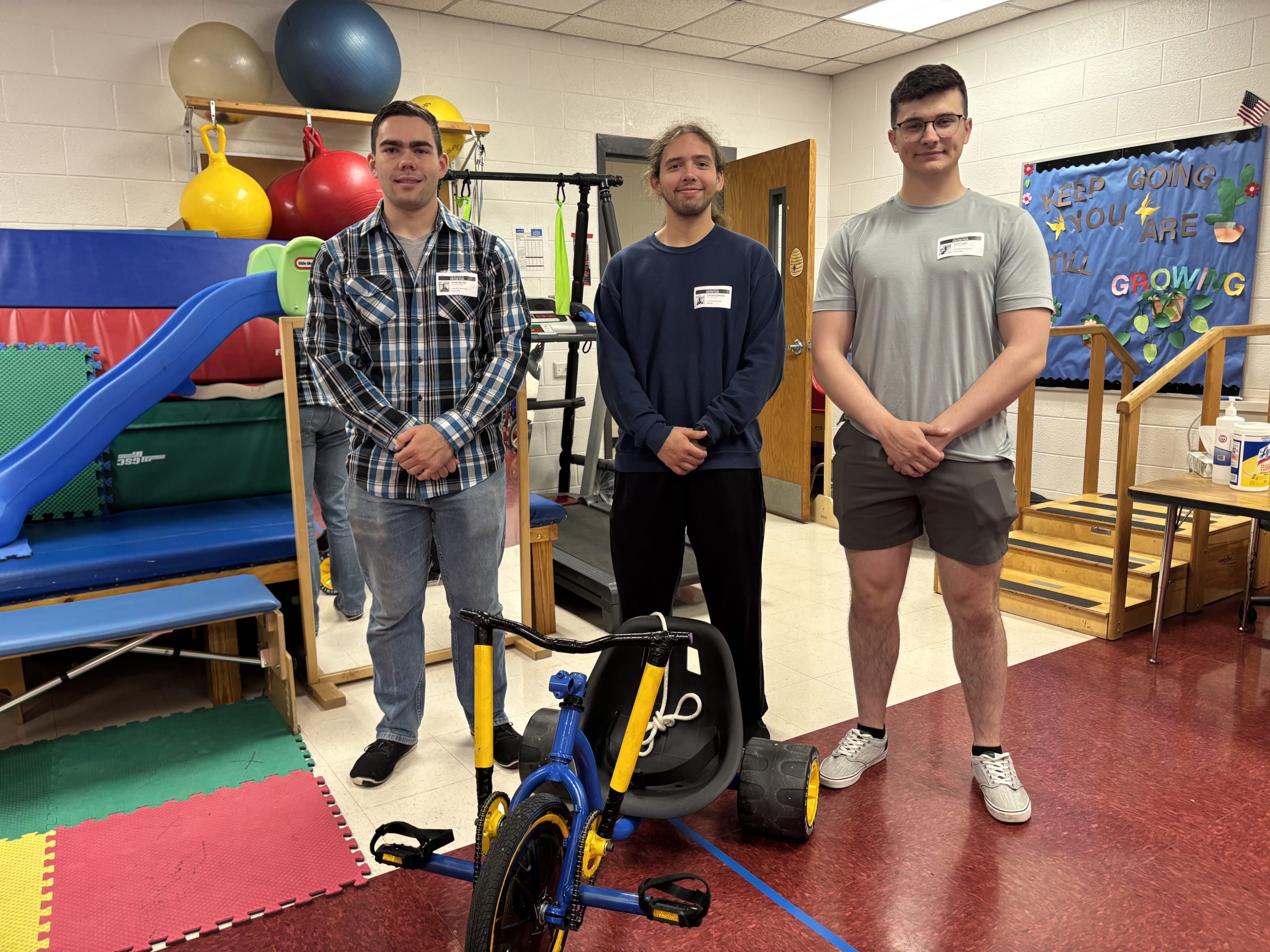
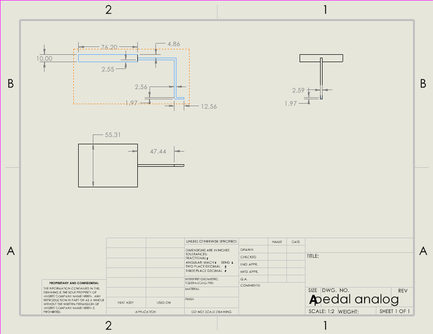
In order to use the bike safely, make sure that both the feet and waistband our snug on the user. If you are the guardian of the user, take up the leash to ensure that don’t get too far too fast. If needed, use the T bar at the bike of the bike to give the user a push off and let them begin the pushing rowing motion to propel the bike forward. The bike can turn so make sure to stop the bike using the leash before they collide with a wall. Have fun!
The project came together really well. Our planning in the early stages of how we wanted to propel the bike forward came together smooth. We had to adjust a little while manufacturing everything. Mainly the fact that the bike is now push instead of pull, the bike moves a lot faster when we used gear ratios, and the bike seat needed adjusting to the frame of the bike. We also learned that when you weld any parts it should be something that can be machined down to size that way the parts fit together better. In the end the only real problem on the bike was how the gears lined up. They were a little offset due to the machining of certain parts and the welding. In further generations of this bike we can machine the parts better, add in a 3rd gear on each side to reverse the direction and make it a rowing motion, and rely a little less on welding parts.