This group is improving and redesigning when necessary a prosthetic attachment for a girl who wants to play percussion. The first five weeks were spent catching up with the prior group on what had happened and what was redesigned and then showing the family the final prototype from the previous semesters. Our current focus is adding other improvements using data from a previous semester’s group, while still keeping the primary objective of creating a safe and independent attachment design.
Our client is a bilateral amputee, and they currently request drumming attachments for the right and left arms that can accurately play band instrument like a normal arm. Although an attachment was created for a drumstick, its design is difficult to work with, and can be used for only one kind of instrument. Following feedback from the previous group, modifications need to be made most specifically towards the attachment areas. The arms would need to have a reliable way to tighten with little or no assistance from hands, and their attachments should be made with the same specifications in mind. A final design needs to be made that can allow for greater independence, multi-variety, and withstand drumming motions with no deformation for long periods of time.
We’ve been researching various ways to make an efficient design, and we’ve also been in contact with the previous group to gain insights into their design processes from the last semester. This pointed us towards editing the locking mechanism, slimming down the base attachment area, and improving the attachment’s neck.
For the locking mechanism: when the arms play with drums, muscles in the arm are able to resist and recoil when the drumstick hits. The biggest complaint noted from the client’s original test run is that although she is able to play well, the drumstick’s strikes are rather stiff. One suggestion came from using a tension spring; assuming it could reliably fit into the attachment, the harder the drummer played, the harder the spring would kick back. The neck of the attachment would need to be thickened for this design, but otherwise could still withstand 10 lbs of force and move 360 degrees.
The attachment is currently being held by a spring which is screwed to the base of the arm’s end. The spring offers good flexibility, but is incredibly difficult to insert and remove other attachments with it. We have decided to add a weaker spring for better maintenance and usability.
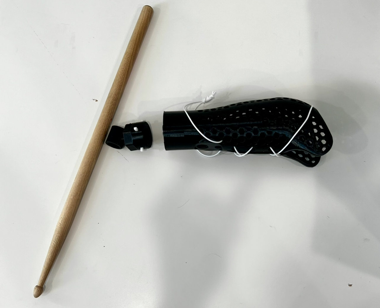
The first design involves increasing the slot width for the prongs in the locking mechanism. Assuming the arm’s end were to be slotted down, it would be easier to secure the attachment in a place far easier.
A second solution involves removing the depth from the J hooks. It would still be possible to lock the attachment in while preventing an extreme amount of force from being used. This will depend on the spring’s compression at the beginning of the lock.
One potential issue to both is that while our client plays, the mechanism could very well come loose if enough force is applied. This will be somewhat mitigated with the strength of the spring, but it is an important consideration.
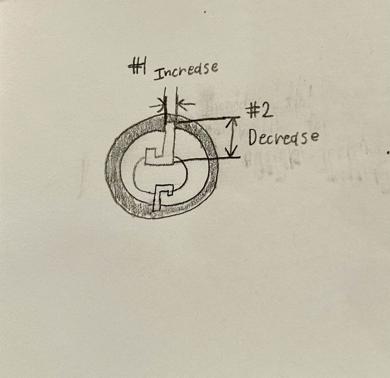
The second design idea involves slotting a rod through the spring, making the arm’s end larger, and the fixing the lock-prongs to the attachment.
The rod would mainly serve to keep the spring in place. The attachment will be hollowed out to fit the rod, and would serve as a secondary lock.
As there were difficulties inserting the attachment originally. This design will include a wider diameter for the attachment to be inserted. About a millimeter would be taken off of the diameter — enough to allow easy insertion. Even as adults we had difficulty inserting the attachment at its current state!
The original design included a metal attachment with the prongs that was inserted mid-print. This creates a bit of wiggle room which can lead to deformations later on. We would like to fix the prongs to the attachment so the drumming motion is more relied on by the spring. The processes for attachment would remain the same.
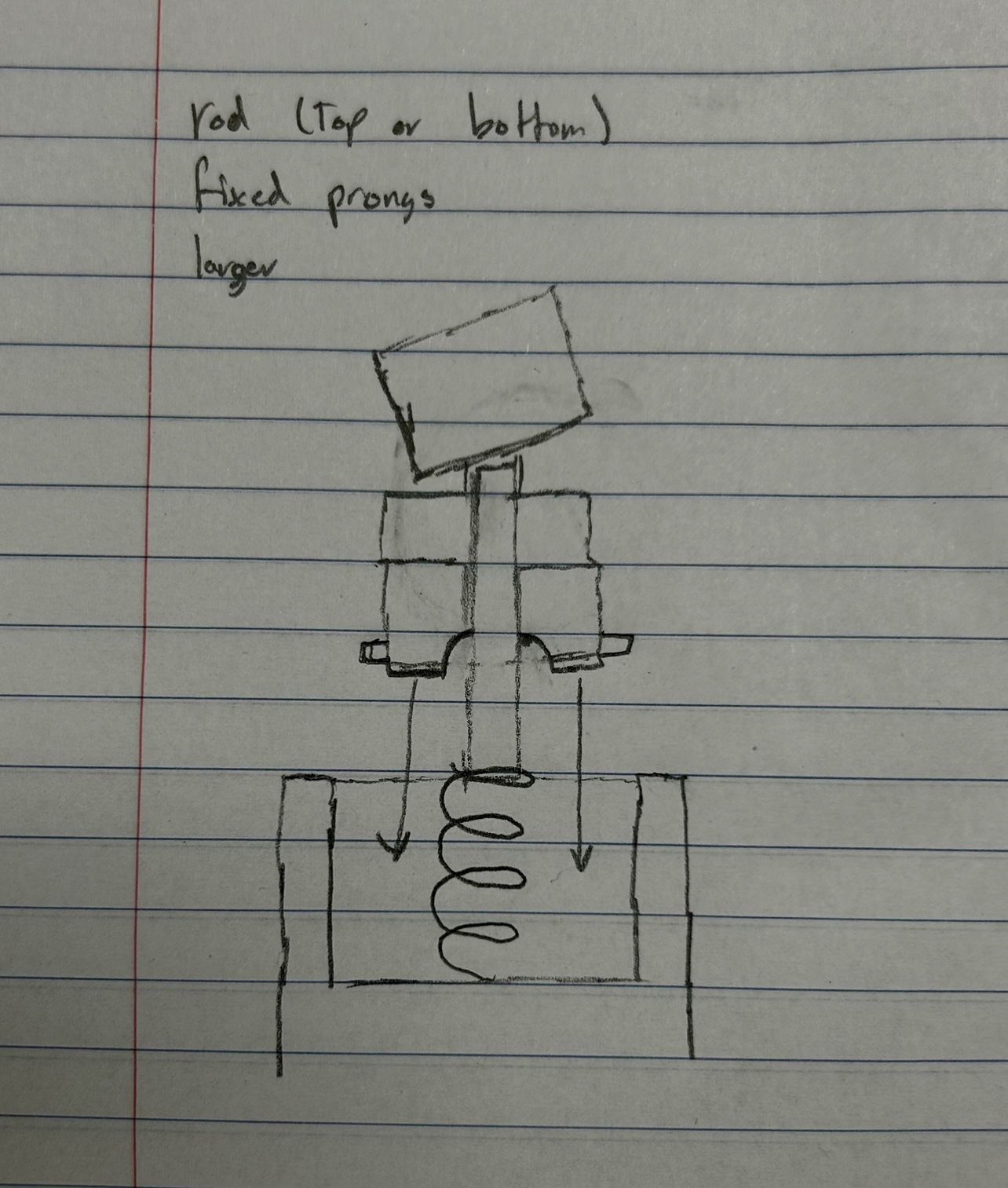
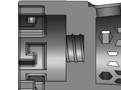
The third design idea involves the instrument attachment that fits into the arm’s slot. It uses the J hooks to center and attach the two components. This part is at the end of the arm and will experience some of the most stress during use. We want to make it as strong as possible without inhibiting functionality.
The original design included a circular part that was made to slide in a drumstick to play an instrument. However, the connection or “neck” where that part attaches to the connecting prongs that will be used in the locking mechanism is thin. Adding more material within that area would not only increase the longevity of the attachment but also would be easy to do with minimal added cost due to the attachment piece being 3D printed.
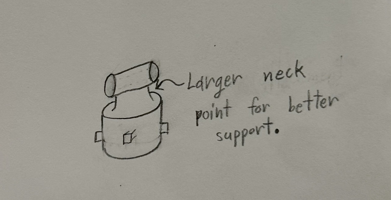
As our project includes the continuation of previous teams’ work, all designs will be taken into consideration while contact with the family is made. At this stage, the focus will be on Concept Design 1, which includes increasing space within the guide slots and improving the pronged attachment tolerance. Wider slots and deeper J-hooks allows for easier attachment of the removable end piece as well as ensuring the piece is secure.
However, as this is the preliminary stage in the process, a broadening or narrowing in design considerations is anticipated following a meeting with the client.

The selected design includes concepts 1 and 3 to improve the existing arm, as well as the inclusion of other attachments that can be used for both percussion and daily use. The J-hooks at the arm’s end have been widened and shortened for a more independent attachment process, and the attachment prongs have been thickened to account for larger forces. Additionally, the drumstick attachment sports a thicker neck with a different shape to make it more stable.
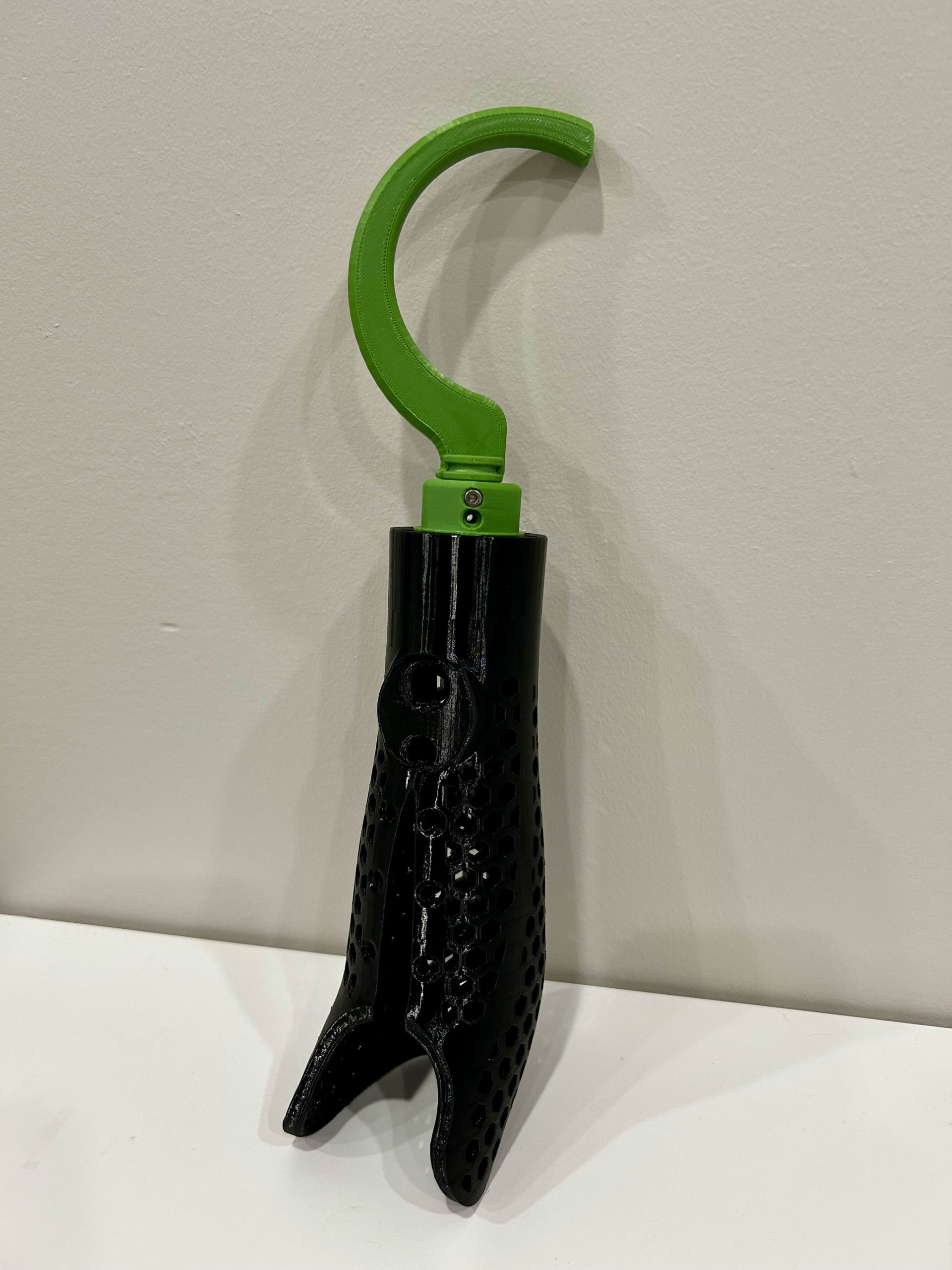
The current attachment designs include a drumstick holder and a hook. The hooks is designed for everyday use, and will be strong enough to pick up a number of common items.
All attachments should be able to be attached and detached reasonably well. They should also comply with limited movement and strength capabilities.
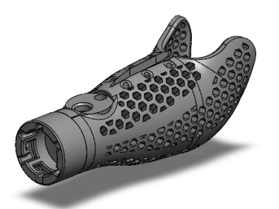
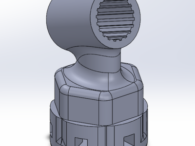
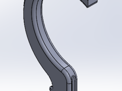
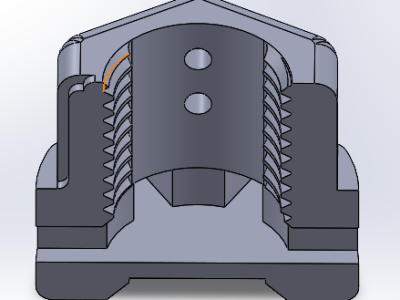
There were a few modifications made to the design from last semester, and we still intend to retain the original functions of the arm to the best of our ability:
Main:
The new design features six wider J-hooks (8 to 6) that have been inserted into the end of the arm, as well as making the J-hooks more shallow where the locking mechanism is meant to fit. This will allow an easier overall attachment process; a new spring has been added inside with less resistance but enough to suitably hold any attachment as necessary. We are still finding a better alternative for keeping the spring in the arm while still being able to remove it in case it gets damaged.
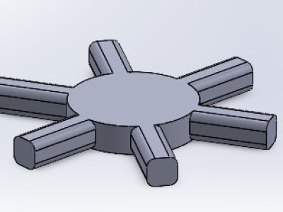
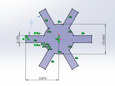
The old locking mechanism has been replaced with an updated design while keeping the idea of the original. The original had a key with 4 thin prongs. The prongs were made of PETG with the rest of the housing being TPU. Under small forces, the prong was enough to hold its shape and keep its function. However, by changing the prong cross section and increasing the area of prong it can hold a much larger weight without permanent damage to the key’s prongs.
The new design with six prongs has its prongs offset by 60 degrees and is made of ABS plastic. The key’s prongs now have a height and width of 0.2 inches compared to the previous design’s 0.125 inches. This will disperse the forces of whatever attachment onto two of the larger prongs at all times, whereas before, all the force would be on a single thing prong for the majority of activities. The attachment’s spring docking end has been chamfered to allow easier spring alignment to the attachment. We will continue to test and stress any new attachment parts we make. Due to the attachments and the arm itself being 3D printed we can change many settings to increase strength as well as durability. For example, the amount of exterior walls and infill volume can all be changed without having to make the whole part from scratch each time. Allow for faster and reliable testing.
Drum/Marimba:
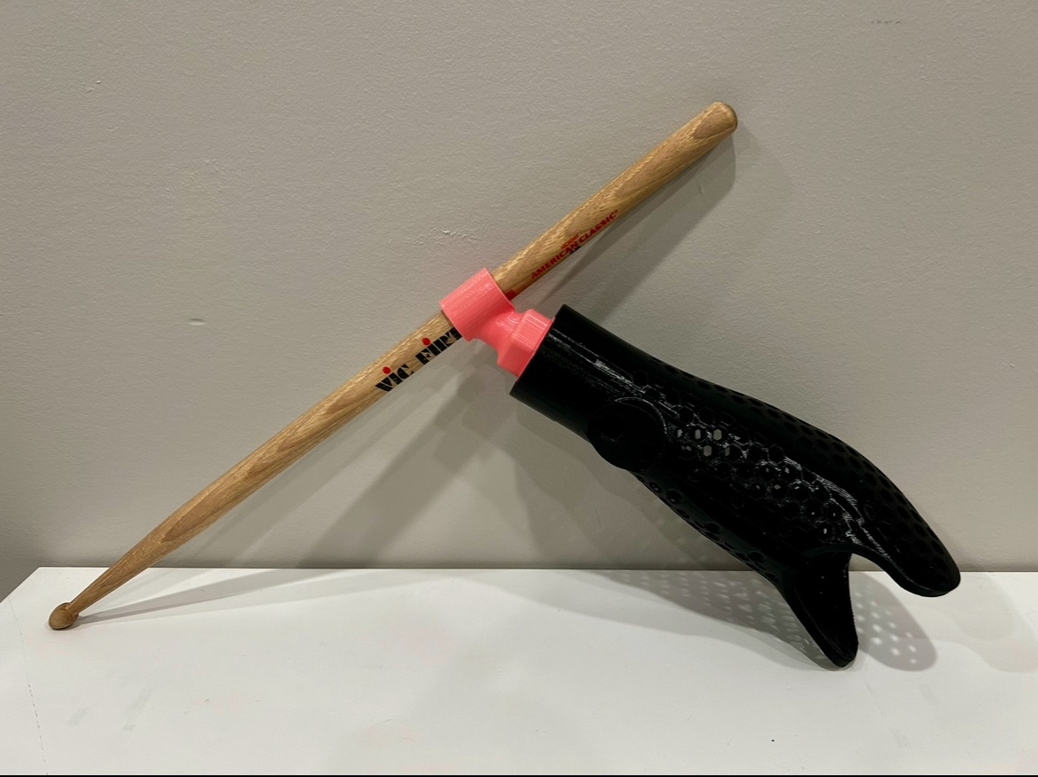
The neck of the attachment has been thickened to reduce the twisting motion and has been converted to a filleted hexagon to allow for a better grip without having sharp edges. It also received the larger prongs to match with the current J-hooks and for later testing. We plan to have more diameters available so that more percussion instruments can become options. Currently, there is not an indicating line or arrow to help with alignment due to the orientation of playing the drums. This will be added soon to improve the user experience.
Hook:
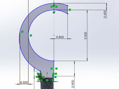
Our first attachment includes a hook 4 inches long for grabbing or moving objects. It is a common concept for prosthetic attachments, but our goal was to almost entirely 3D print it so that almost no hardware is required. The current design only takes 2-4 screws to lock in the mechanism for safety. A problem that occurred was having difficulty determining when the attachment was set in the arm by feeling alone. An indicating line has been added to the side of the hook to see if the lock and attachment(s) have been aligned correctly. The inside of the hook has more material, and the base of the hook has added material to reduce plastic deformation vertically. It is to be screwed into the attachment end, and has two screw holes, and two slot pieces slotted on the sides of the hook to prevent unnecessary rotation. Parts of the hook have been filleted to reduce rubbing and other stress risers. All parts making the hook attachment are designed to be disassembled for easy cleaning.
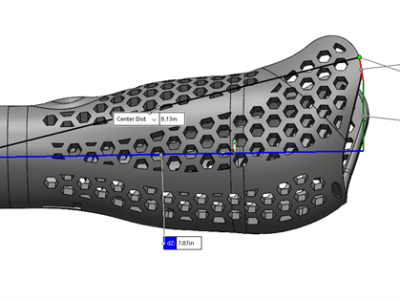
*The goal of each analysis is to apply different effects that go beyond typical means*
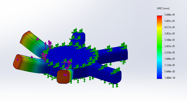
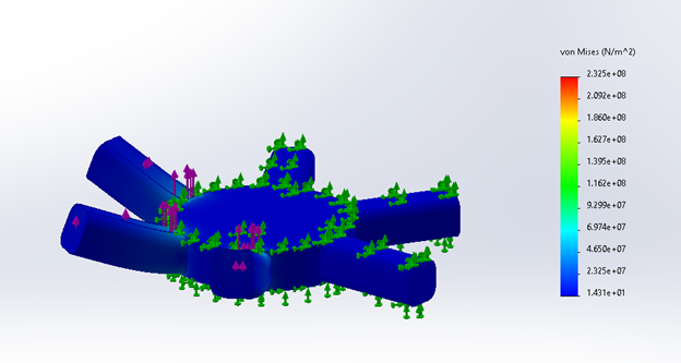
For the first engineering analysis, we are taking a look at the forces applied to the key lock. Because the key’s prongs could break or deform. At the very least, each hook needs to be able to support a maximum load in the event the angle of the attachment is altered. We assumed a fixed position for the key and afflicted three prongs for a realistic comparison. The prongs may move up to 0.2165 inches (0.55mm), and stress levels across the part are small. Other issues found during prototype testing can be altered by increasing prong thickness slightly and increasing fill density.
Tested using a 30 LBF shear force on ABS plastic, SOLIDWORKS.
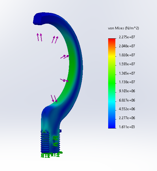
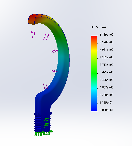
For the second engineering analysis, we examined one of the prototypes. Previous testing before modifications had been made noted plastic deformation on the inside of the hook using a ~30-lb contact force. With an improved vertical thickness of 0.8 inches (20.32mm) just after the threads. FEA tests indicate Von Mises stresses primarily along the inside of the hook and threads. Lesser forces are also noted along the hook’s spine. Plastic deformation will most likely occur at the hook’s tip up to 0.2362 inches (6mm). A previous test held a sustained load of 30 LBF without complete failure, which future models should prove enough for most day-to-day operations.
Tested using 30 LBF or 133 N on ABS plastic, SOLIDWORKS.
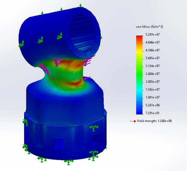
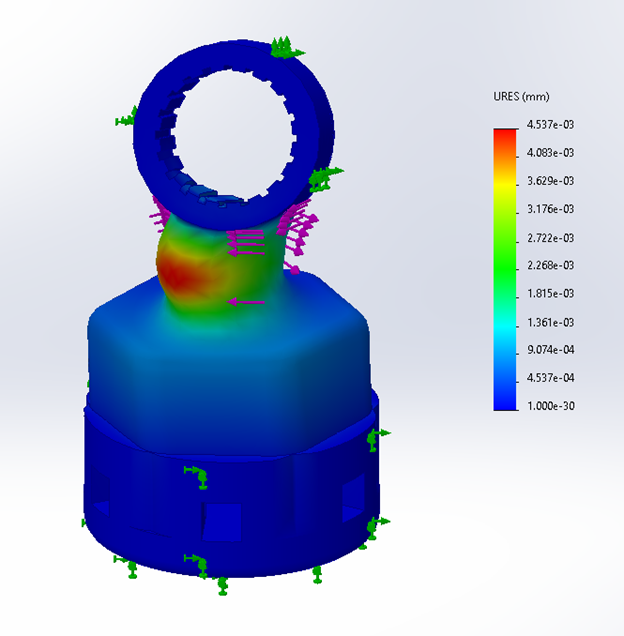
For the third engineering analysis, we documented the twisting motion caused by a repeated drumming motion at the end of the attachment. The base of the drum is subjected to the maximum torque an average human hand can apply to any surface. As the drumstick hits a surface, the neck will twist back and forth until motion has stopped. FEA analysis indicates a maximum displacement of 4.537*10^-3 mm.
Fatigue induced over a period of years is still a concern, especially at the neck’s midsection – the thinnest portion of the attachment. The fill pattern will have to be adjusted to reduce fracture.
Tested using ~177 LBF-in or 20 N-m on Silicon, SOLIDWORKS.
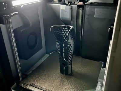
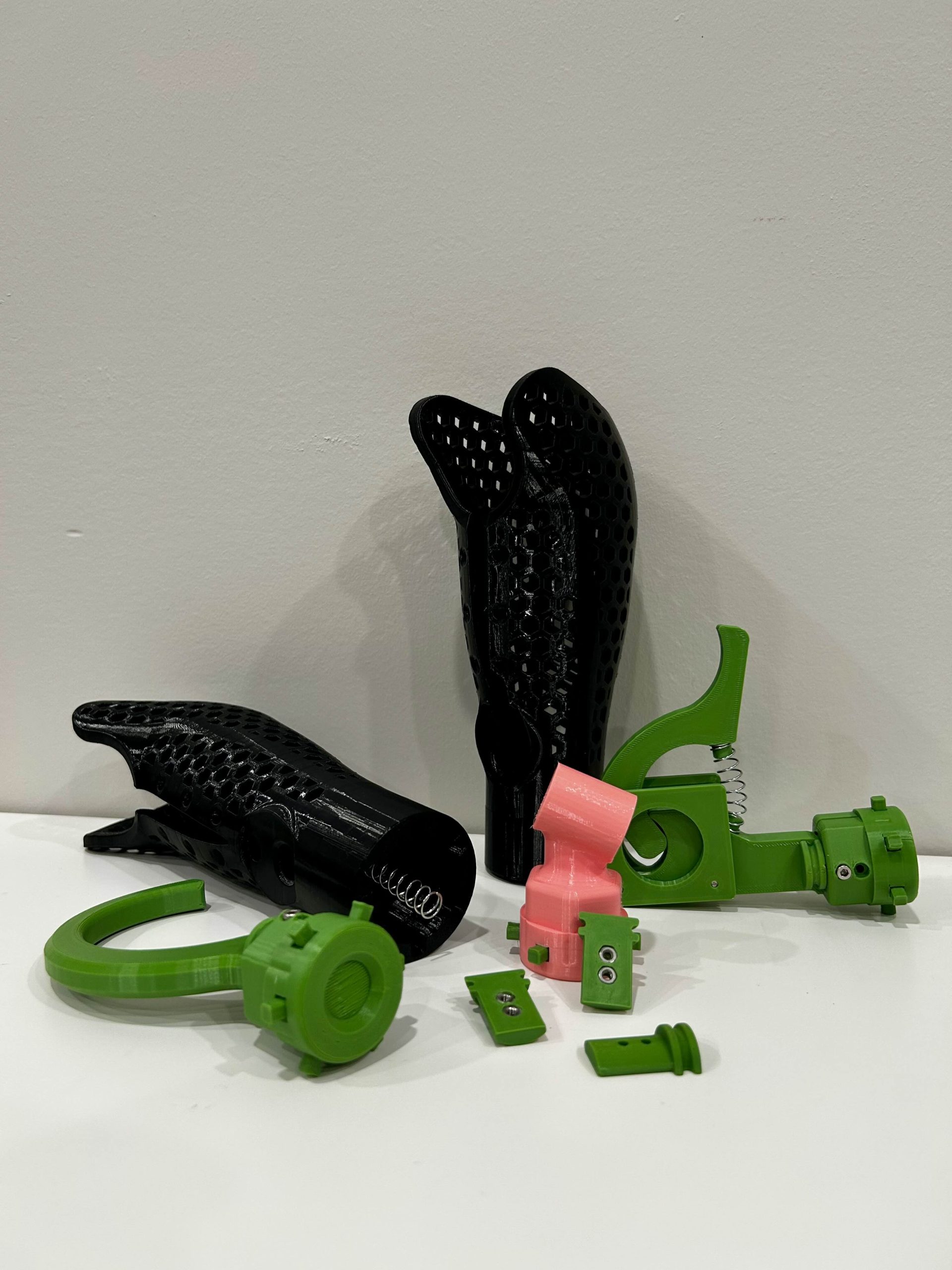
A key element of designing any prosthetic is ensuring it fits securely and comfortably. This can be difficult to manufacture traditionally due to the detailed geometry that is made for one particular person, as well as what materials you can use to make the prosthetic. For these reasons, our group decided to manufacture all the components with a 3D printer. Excluding the springs and the occasional screw. 3D printing allows us to pick what material would work best for which part. For the actual arm part that would be attached to our client, we went with a 95A flexible TPU material. The 95A TPU is the black material that makes up both arms, which can be seen in the completed section. This will allow for when the area expands and contracts as our client moves. We also found a particular brand of TPU that is a medical-grade certified material, so it will not irritate our client while using it. We want it to be functional but also comfortable for extended use. Since we made each attachment to the arm separate, we were able to make it out of any material we believed to best fit our use cases.
The hook was printed completely with ABS. This is due to its higher temperature resistance as well as impact resistance. It is a ductile material, so if it gets over-stressed, it will change color in those areas to warn our client of any damage. Due to the nature of 3D printing, we can inlay other parts during the printing process to ensure the strongest configuration. This was done with the attachment hub that the hook and writing attachment use to attach to the main TPU prosthetic. The attachment hub has a few options to screw in some M3 screws to ensure all components are fully attached to the hub. Finally, the last ABS printed parts are the shims that are used to lock in any attachment that fits into the attachment hub. After the shims were printed we used gorilla glue to M3 nuts that are inserted to allow the attachment screws to always stay allied while not relying on the ABS to solely hold the screws in by friction. If you let the hole be the size of the screw with no nut then it can wear out the material and over time make the hole bigger and unsurable. With the metal nut, this can be avoided. In the final printed parts area, all ABS printed parts are in green.
The last material that was used was a different TPU. The material used to create the drumstick attachment needed to be flexible, and the TPU used for the arm was just too stiff to get the movement we needed without compromising the integrity of the attachment itself. So we modeled it so the component would be built strong, but with 90A TPU, which is the next grade of TPU, meaning it is softer. This can be distinctly seen in what we like to call bubble gum pink. Thanks to the ability of 3D printing to inlay other parts, we were able to install an ABS key, which is the green parts sticking out of the attachment. This way the locking mechanism can have to structure and rigidity of ABS while the extension can have all the properties of a softer, more flexible material.
Drumming Attachment:
The testing for this phase included attempting to reach a paradiddle (multiple notes per hit), and stress testing the attachment using the drumstick as a torque attachment. Previously, the drumhead was wrenched off after two full rotations. Currently signs of deformation have occurred to the neck, and it’s ductility has been continuous. Because the TPU for our updated prints is softer, it has an easier time reaching that kickback motion we’ve attempted to achieve for a while now.
Hook:
Strength: Tested using a 30 LBF across the hook’s interior. A number of fractures were observed across the entirety of the hook’s interior. All stress concentrations are where they are intended to be, and the hooks themselves are able to be used at any orientation. For the final print, an maximum of 45 LBF can be applied to a singular hook. Anything more risks damaging the key mechanism and the threads on the inside of the hook.
Dexterity: Without wrist motion, lift and carry basic items using two hooks on the left and right side prosthetics. The hooks themselves have little difficulty with most common items. The only considerations are that practice will be required to maneuver the hooks using one’s shoulders, and that there may be trouble holding objects less than 5 cm with precision.
Utensil Holder:
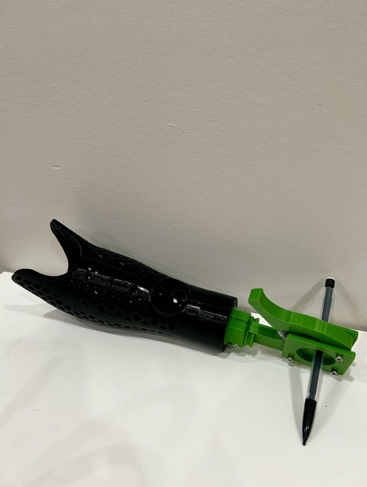
Using our own arms colinear to the prosthetic, both prosthetic arms have little difficulty writing without wrist movement. The spring mechanism is strong enough to prevent slippage of objects from excessive force. If using a mechanical pencil, it would be possible to adjust the lead by pressuring the end. The only considerations are that the insertion angle needs to remain at the top two hooks for typical writing, and the utensil holder may have trouble holding objects greater than 12mm in diameter. The print parameters are the same as the hook, so durability is secured.
The biggest issue that could occur stems from printing errors. Before the print is finalized, other sharper extrusions should be filled down, especially on the interior. Testing the interior with a makeshift prosthetic sleeve shows minimal irritation. In the event the prosthetic or its attachments are damaged, the orientation of each will not be enough to hurt the user unless intentionally. The arm itself can be leveraged off by another person or by the user itself in the event of constriction.
It is possible for bacteria and dirt to reside in the 3D prints’ pores. After removing the springs from the arm and the utensil, the interior and exterior of each should be sprayed with a vapor disinfectant or another cleaner such as soap and water – but no harsh chemicals that could damage the skin – . A prosthetic sleeve should prevent most skin bacteria, but the attachments themselves will be handled by other people. The cleaning period is directly related to the intensity of the activities the user performs, and is up to the user to determine when they would want to clean their prosthetic and attachments.
The goal of this was to improve the usefulness and quality of the arm. Modifications were made to the original model and new attachments were created with this in mind.
We first started out with simply modifying what originally existed. We found that the neck of the drumming attachment to be a point of failure, and the original j-hooks weren’t deep enough to support the attachment properly; additionally, the prongs used to fit into the hooks were narrow and liable to wear.
To fix these, the neck was thickened, and an elliptical cross section was used instead of circular. This strengthened the neck under torsion, which was the primary motion of the part. The neck was also printed using a softer-grade TPU to allow for paradiddle, which is the bounce a drumstick experiences after hitting the drum. As for the prongs and j-hooks, the prongs were thickened and the j-hooks deepened, allowing a sturdier and more secure connection between attachments and the base arm.
Additionally, two new attachments were created; a hook and a utensil holder. The hook is a relatively simple design, useful for grabbing or carrying objects, or opening doors or drawers. The utensil holder is a clamp to use for writing or eating, designed to hold a pencil or fork of any size. Both new attachments were made with sturdier ABS filament to provide more strength.
The arms could be improved greater with feedback from an amputee, but the current improvements make the arm more reliable and allow use for a wider variety of situations.