Spring 2025 Project 04b: Wheel Chair Games (Team B)
Abstract
Our student is an adventurous, independent 5-year-old girl with cerebral palsy at Findley Elementary School. Her playground is mulched with rubber tires, making it entirely inaccessible to her. She has excellent upper body mobility, and frequently uses a walker or crawls, so we are tasked with improving the accessibility of the playground so she can play with her peers and release some energy during recess.
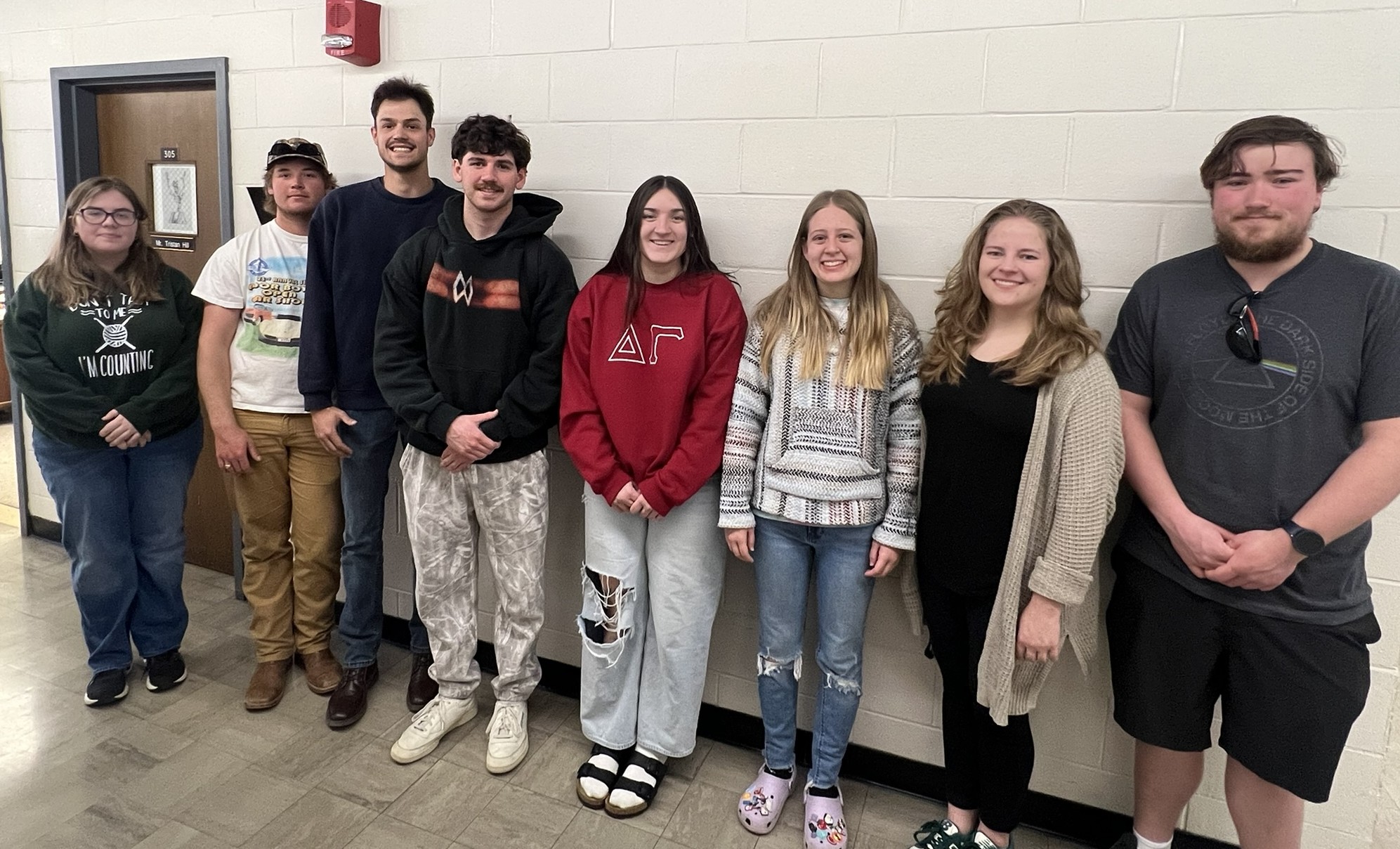
Anna Sublette, Slade Pratt, Braden Marcum, Cole Gibson, Zoya Kopesky, Syd Potter, Rene Rooker, and Sam Loparo
Problem Statement
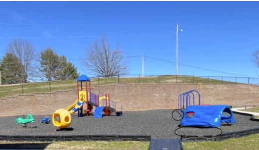
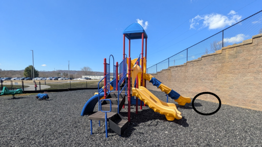
Findlay Elementary School playground is currently not accessible to children who require mobility aids. There are a number of existing structures at recess that our student would like to play with, but she currently cannot access them due to the sharp rubber mulching. We are considering a variety of solutions to give our student access so that she can play without aid, in the same way her able-bodied peers can
Design Specifications
Specifications:
The equipment must be able to be transported to the site and assembled. After speaking to school administrators, we determined that this would be a semi-permanent installation, so we must design equipment to be used outdoors, year around, daily, with minimal maintenance, for ~2 years.
Safety is a significant priority, and we must account for children potentially climbing/using equipment inappropriately at recess, or for impact/collision with our equipment.
A path to existing equipment must be both comfortable to crawl on, yet rigid enough to be wheelchair accessible without physical exertion, and follow ADA regulations for width and ATSM standards for playground impact attenuation.
Features:
Our student should have activities available to her that she can use independently
Our design should incorporate both static and active components, we firmly believe recess is an active event necessary for students to release energy, and our student shouldn’t be deprived of that.
There are some unique aspects to the project, in that we have several minor changes we want to implement regardless of chosen concept design, namely:
A bar above the top of the slide so our child can position her legs unassisted
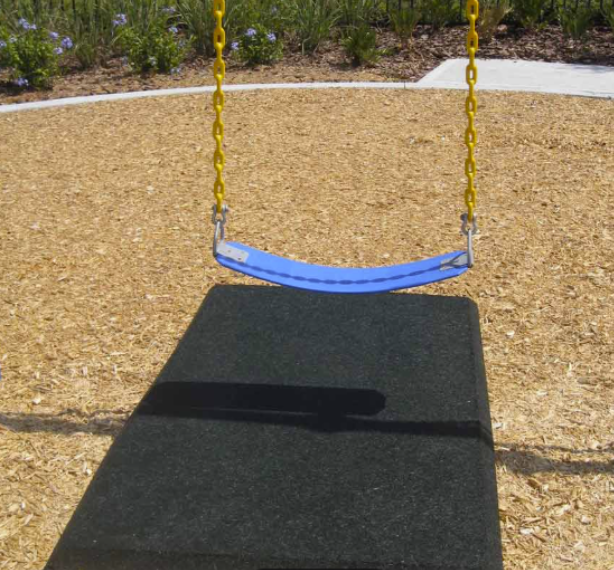
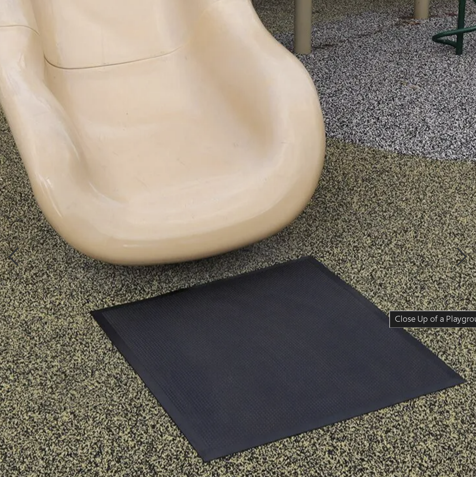
Several “crash pads” placed strategically so our child can get out of her wheelchair without falling onto grass, concrete, or other injurious surfaces.
Background Research
To begin, we researched lots of accessible playground equipment, focusing on both stationery and active elements. Once we met our student, it became clear she could play on existing equipment, she just needed a path to get there, and some minor modifications. This caused a major pivot in our design, so we began researching playground surfacing.
The US Access Board did a study in 2012 on the longevity, wear, cost, and maintenance of 3 main surfacing techniques in accessible playgrounds. All options require a two-layer installation process with something to minimize the migration or deformation of the base layer over time. The US Access Board notably concluded that cost of materials is not necessarily an indicator of performance or longevity. The 3 methods we are considering are summarized as follows:
Unitary paths; most commonly, pour-in-place rubber. The base layer and wear layer are held together by a binder. This typically requires professional installation and is similar to concrete pouring.
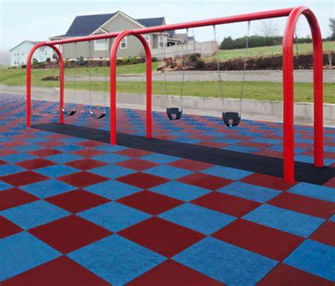
Tile Paths; standard tiles are available for purchase in various sizes and thicknesses, depending on the need.
Hybrid paths; comprised of multiple layers, usually with a spongy base surface and a carpet/mat as a top layer. Not very standardized, considered middle of the road option in terms of cost.
Concept Design 1
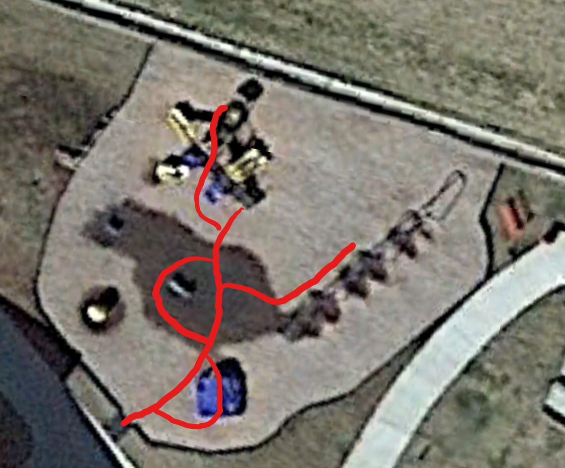
Research for concept design 1 included crash pads. We determined the best locations to be under the slide and swings (in the event of falls), and at the entrances to the mulched area and the main play structure (for wheelchair transfers). We need to find a cost-effective soft foam that has enough drainage, and is mold and mildew resistant, while still cushioning against impact. We have done research, but have not finalized a material.
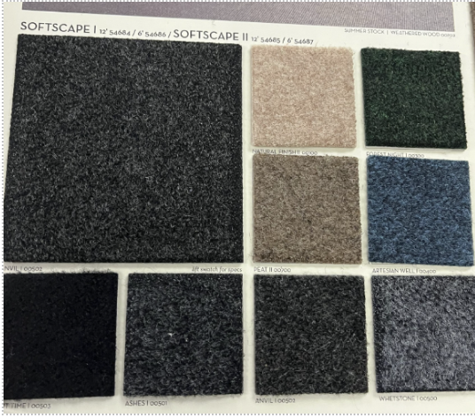
This concept design also covers hybrid path, with the base layer made out of the existing mulched rubber contained in bags to prevent migration and to increase rigidity. On top of the base layer will be a layer of porous foam, followed by a layer of outdoor carpet (or a similar material). This design requires careful material selection to ensure the path remains compliant with our design specifications, specifically in regards to impact attenuation, and the balance between comfort when crawling and ease of wheelchair access. While the base layer promotes drainage, we need to choose a foam and carpet that do not hold water and will not degrade quickly. This is the most cost-effective option, but also requires the most involved design and installation.
Concept Design 2
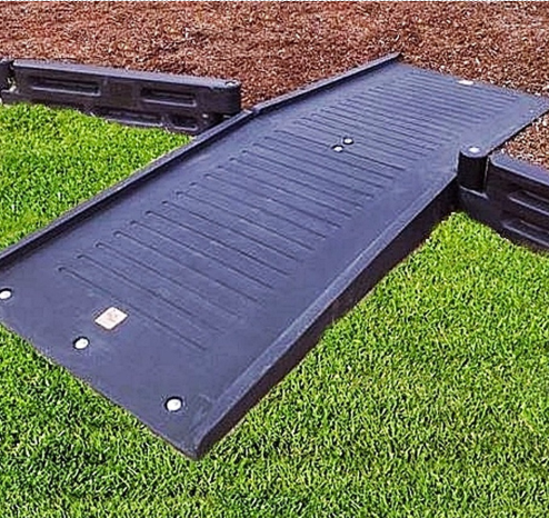
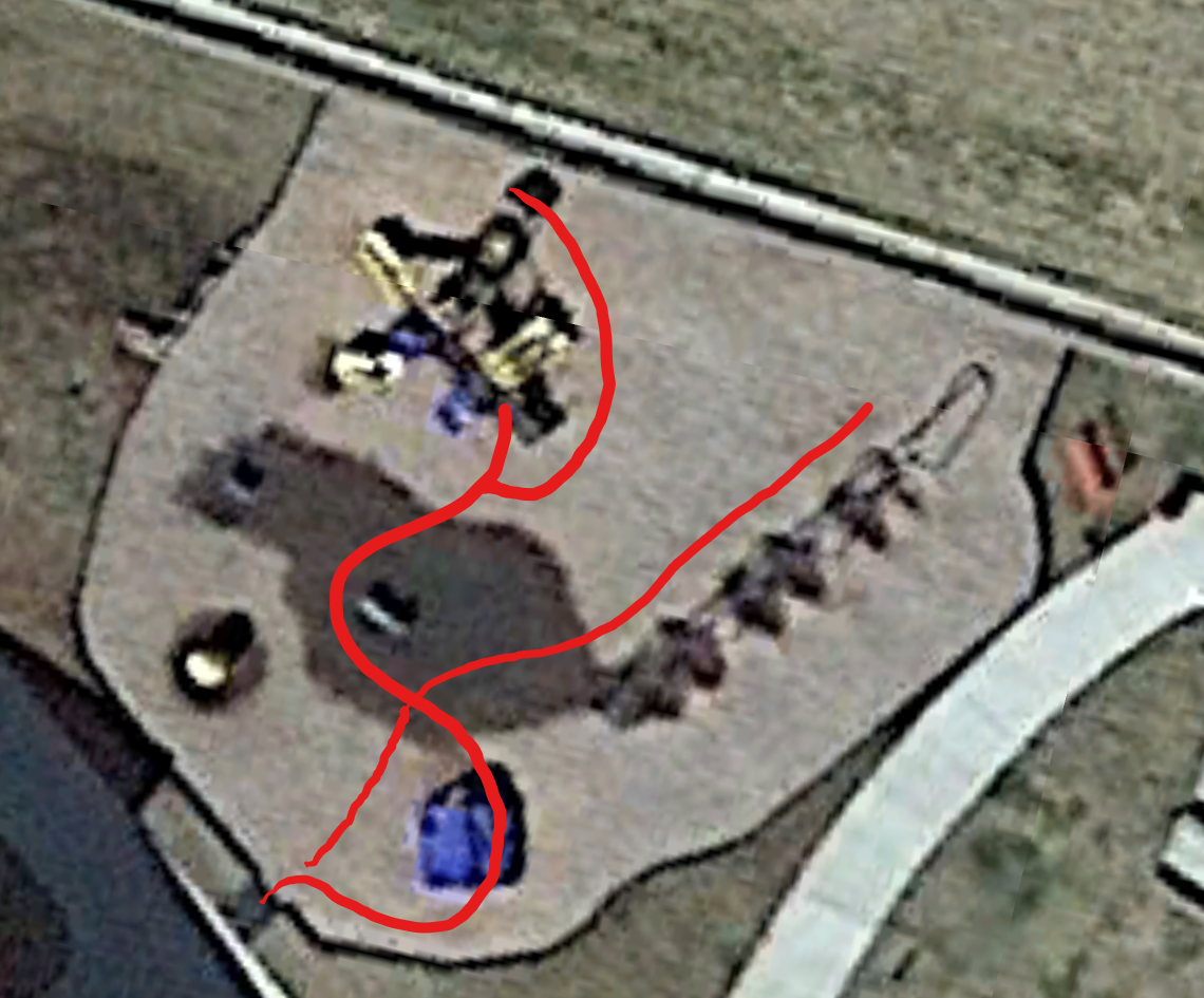
Concept design 2 is to create an accessible pathway from the entrance of the playground to the existing equipment using modular rubber path tiles as the top layer, with the base layer comprised of a wooden frame contained within the footprint of the tiles, and bags of existing rubber mulch within the frame underneath the tiles to provide support and drainage. The US Access Board noted in the aforementioned study that rubber tile paths are prone to tilting when the material underneath them shifts or deforms, which would significantly damage our path, so as with the first concept design, we must ensure the base material does not migrate. Rubber pathing tiles are standardized, and a frame system for the path can be constructed and transported to the site in sections, so this system would not be too challenging to build or install.
Concept Design 3
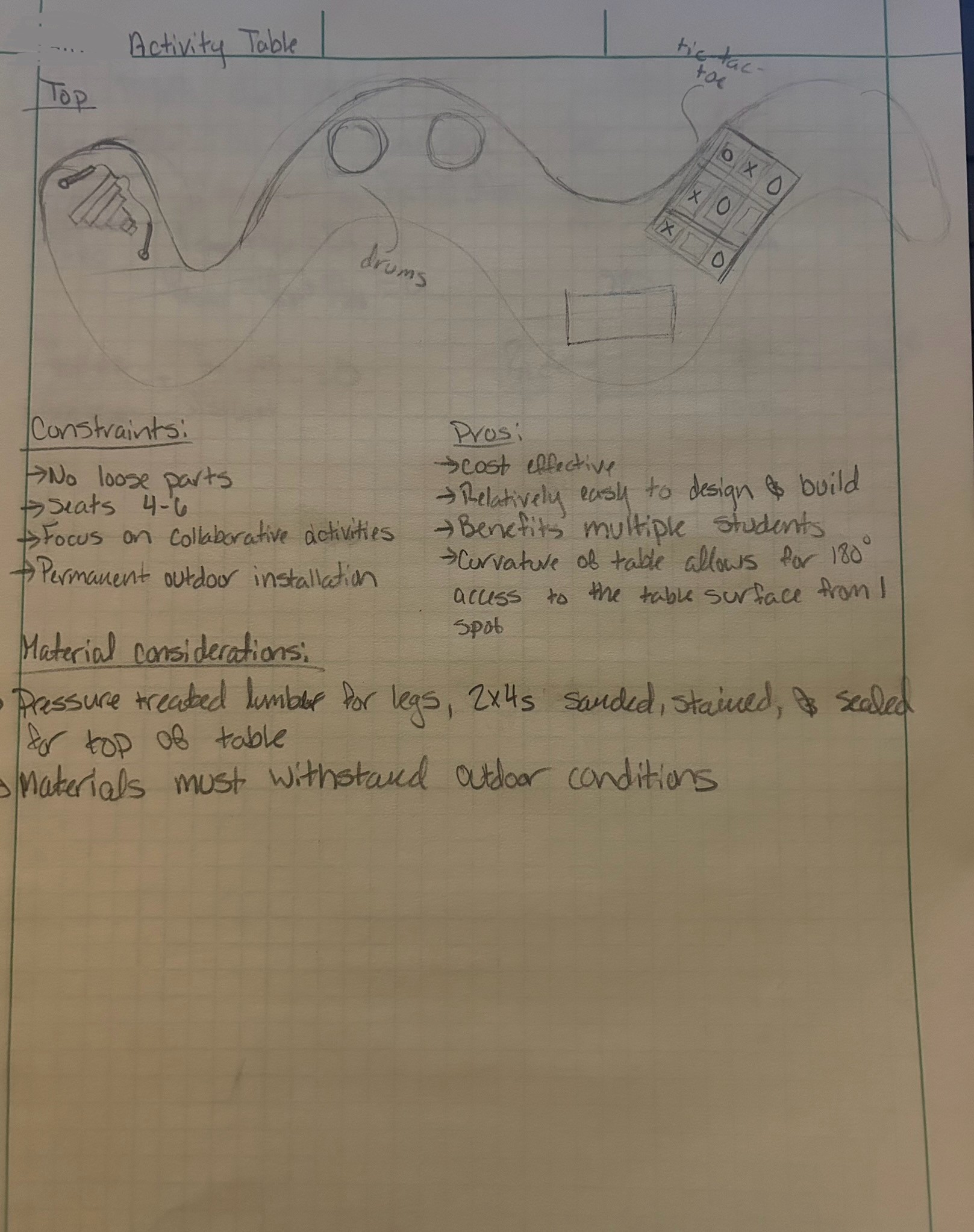
Concept design 3 covers Pour-in-place rubber, as well as our original design for an activity table.
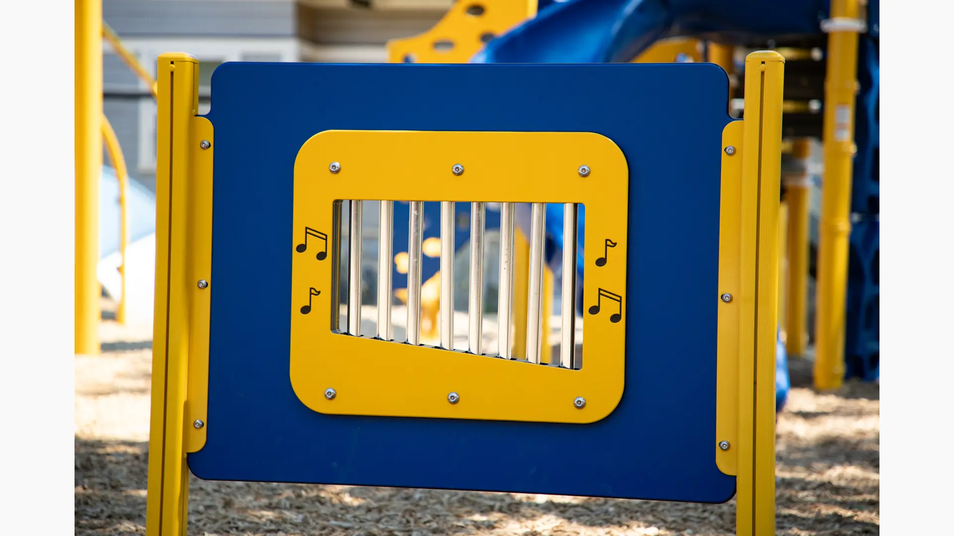
An activity table is a cost-effective, easy way to allow our student to play with her peers. We planned it to allow for 4-6 students to play at a time, featuring 2-4 novel activities, like musical instruments (drums, xylophone), tic tac toe, chalkboard, or a sand box. It is designed to be at wheelchair height, and feature 180 degree access to the table while seated, to maximize the table surface area she is able to reach from one location. From an equity standpoint, an activity table has significant downsides, namely that our student, who loves to play on the swings and go down the slides like all other kindergartners, would still not be able to access the same activities as her peers, despite her being fully capable of using the equipment. We determined that this option would not be the best fit for our student.
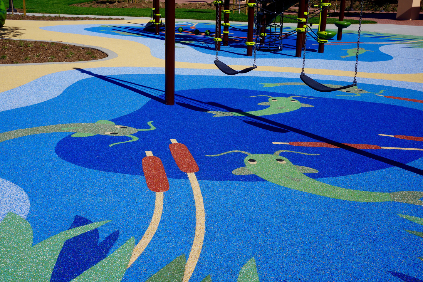
The second aspect covered in this concept design is pour-in-place rubber, a playground surfacing technique that almost always requires professional installation, and is prohibitively expensive. It requires a base layer and a wear layer, with a binder used for adhesion. The result, when installed correctly, is a smooth, unitary surface with the perfect balance of comfort when crawling and ease of wheelchair access. The quote for a path using pour-in-place rubber is in excess of $8,000 though, so this option was also eliminated from our list for that reason.
Selected Concept Design
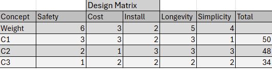
After speaking with our student’s counselor and administration at her school, we were advised to focus on modifying the student’s wheelchair to ensure that she is able to access all of the playground equipment.
Decision Matrix
Overview of Selected Design
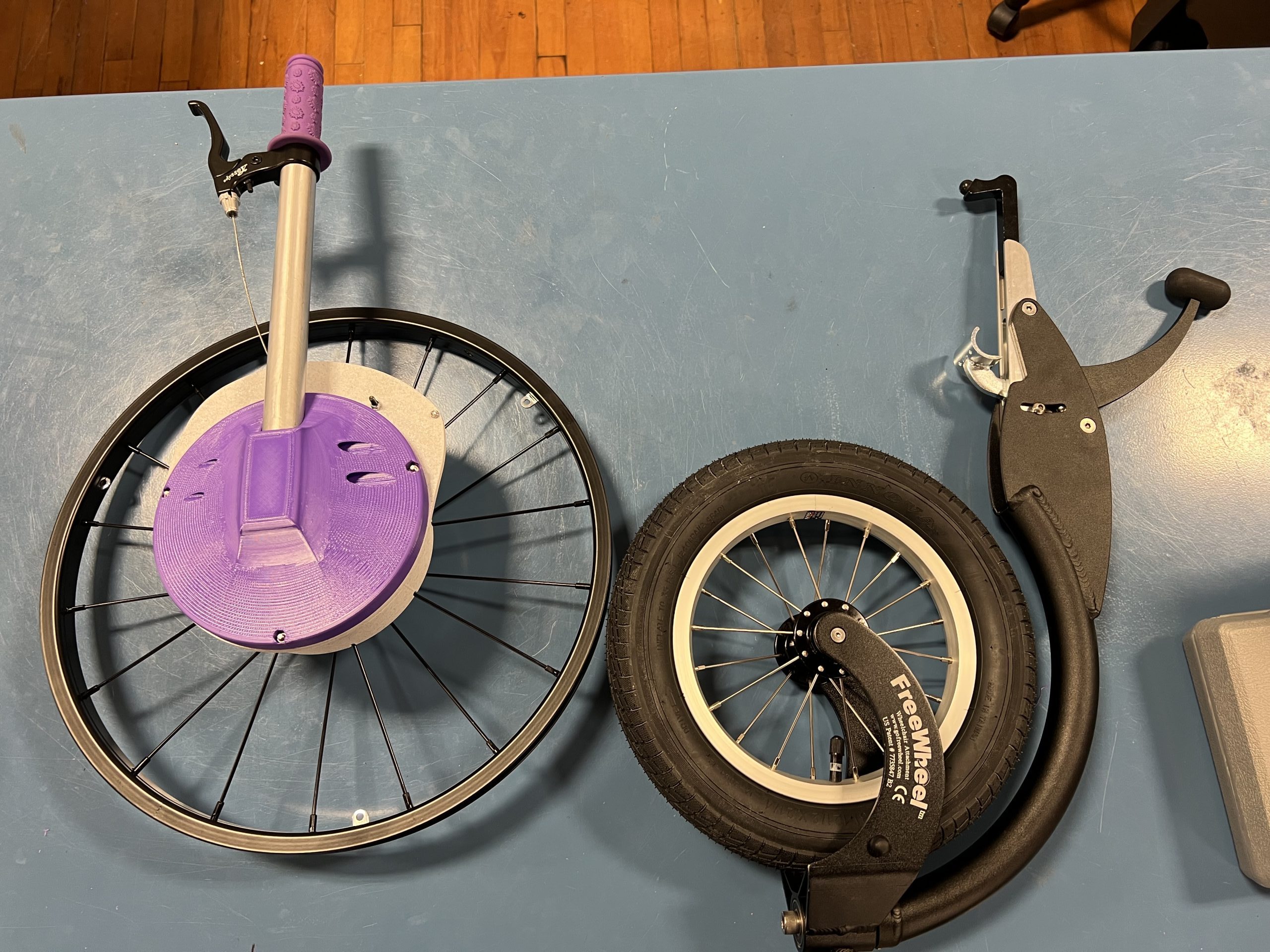
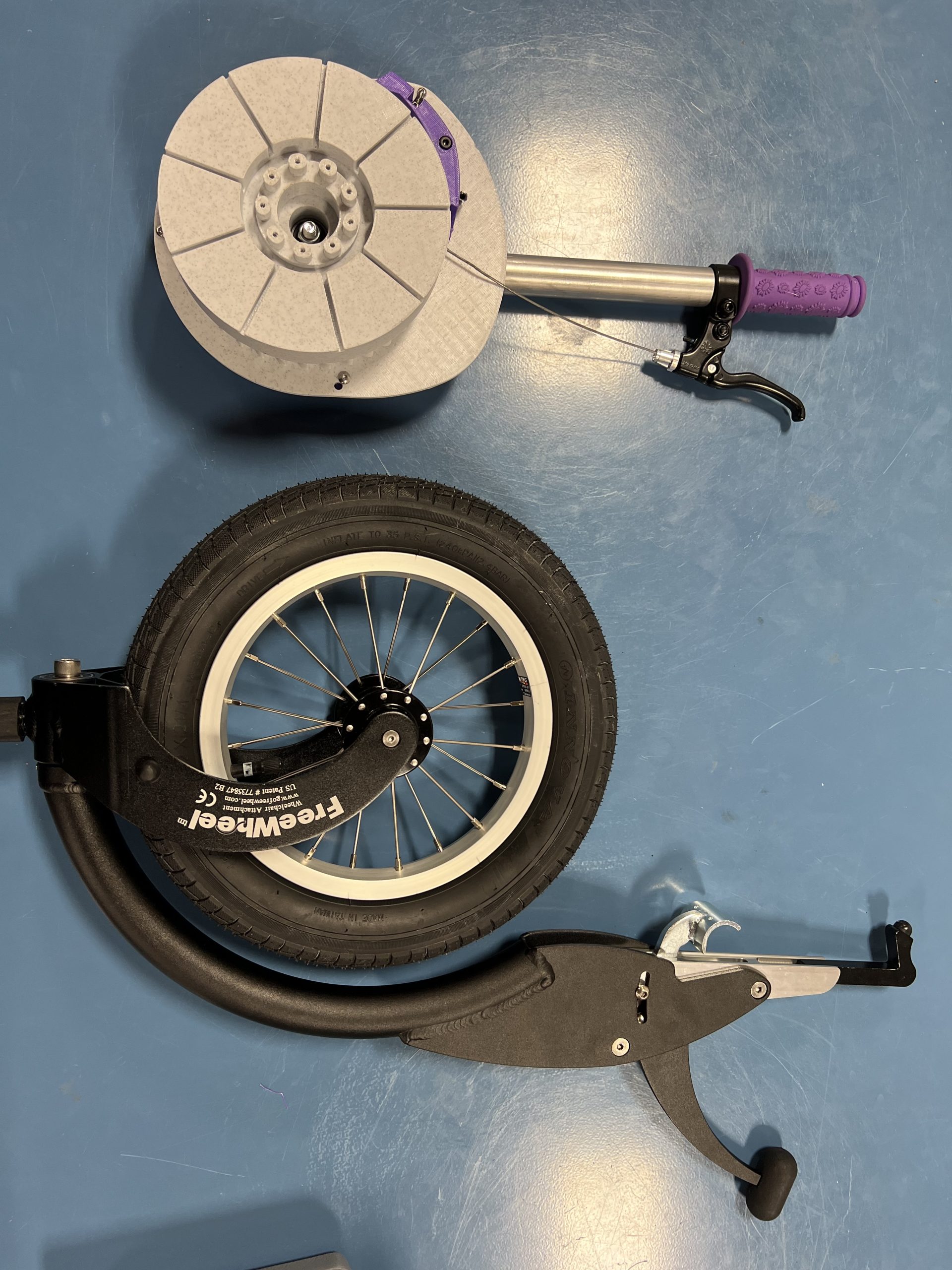
We have had to pivot our design due to the student’s needs as well as time constraints. Our selected design will consist of a third wheel attachment for the front of her wheelchair and a hand drive attachment for the wheelchair to give her easier mobility on different types of terrain.
Describe Design Details
FreeWheel Wheelchair Attachment
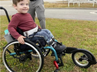
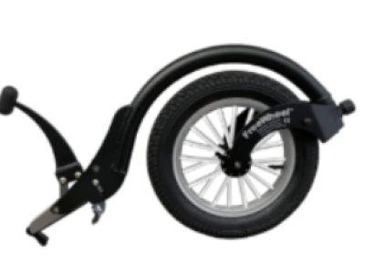
This product clamps onto the front the footrest at the front her wheelchair, in between her feet. After the initial set up, it can be taken on and off in seconds, and is less than 5 pounds, so it is easy to transport. Once attached, the FreeWheel raises the front of the wheelchair up so that the casters are no longer touching the ground. The purpose of this attachment is to give the wheelchair user the ability to go on grass, dirt, gravel, etc. It can also give her the ability to jump curbs, making even more areas accessible.
Hand Drive
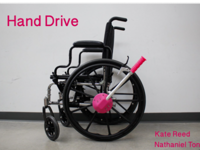
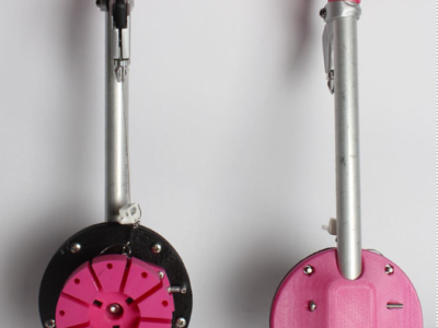
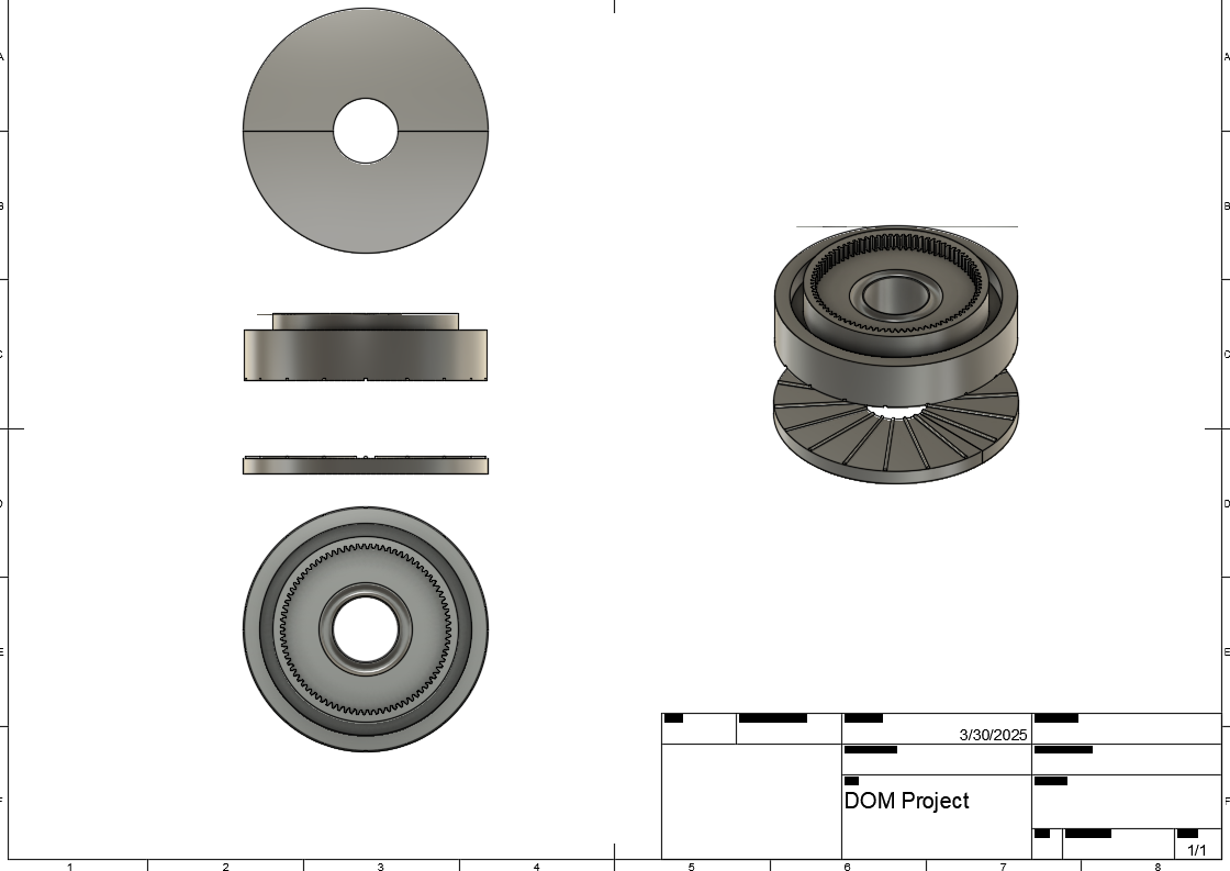
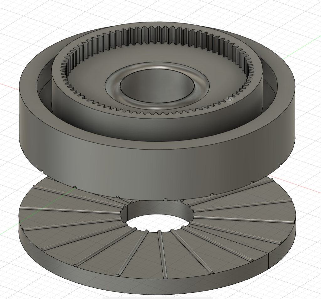
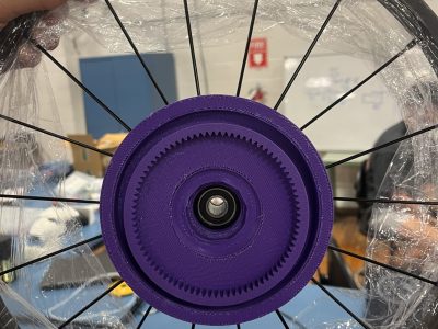
Using and adapting open-source files we will be making attachments so that her wheelchair can become hand drive when needed. This hand drive attachment allows the wheelchair to be powered using a rowing motion. This will use bigger muscle groups, making it easier for her to move her wheelchair. Additionally, her hands will stay cleaner while playing outside because she no longer has to touch her wheels. This hand drive uses a dual ratchet mechanism, so that a break can be squeezed to engage the other ratchet so that the wheelchair can move backwards. We will be adapting this hand drive for our student’s wheels, as well as making sure the handles are small enough for her, since she is so young.
Engineering Analysis 1
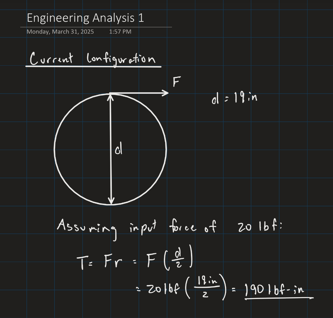
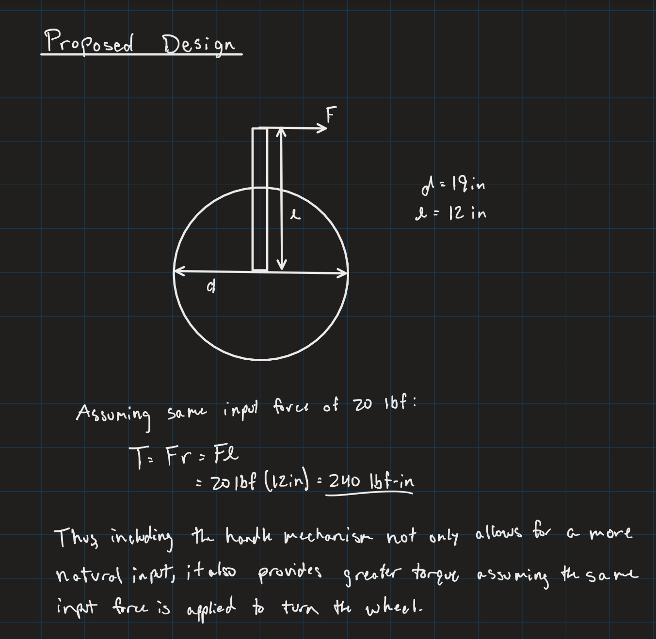
After analyzing the amount of torque that could be output for both the student’s current wheelchair design and our proposed design, it is clear that our design will provide more torque and will allow the student to be able to propel the wheelchair through different terrains with less input force required. The lever arm attachments that we have designed allow for more torque to be applied when turning the wheels compared to the current wheelchair design when assuming the same input force is applied to the wheels.
Engineering Analysis 2
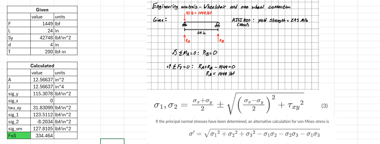
This analysis models the connection point between the one-wheel attachment and the wheelchair. It then does a load analysis on the model to determine stresses and the factor of safety if a Torque is applied using an Excel spreadsheet. As shown in the picture the factor of safety is determined to be a little over 360 suggesting that the attachment is extremely safe but possibly over engineered. Our group came to the conclusion that since the attachment has already been engineered and patented that this is the most likely reason for the high factor of safety.
Engineering Analysis 3
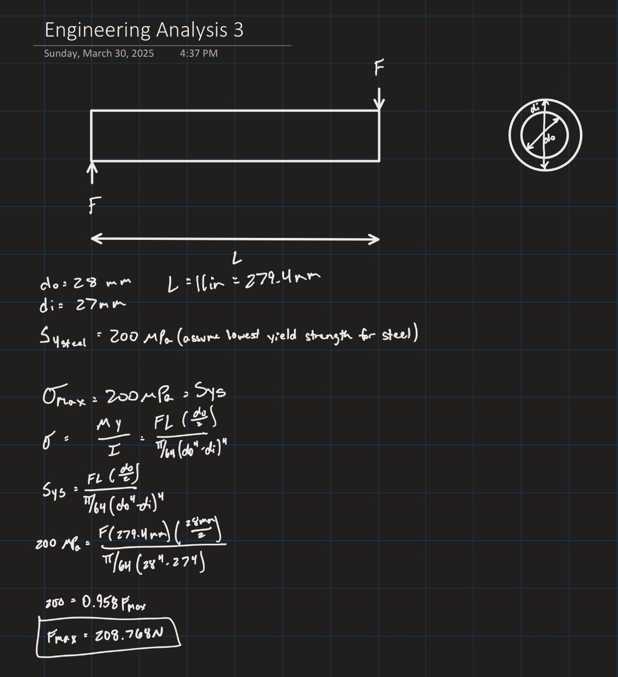
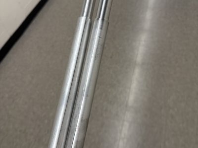
For Engineering Analysis 3, we analyzed the maximum load that the wheelchair’s lever arms could withstand without bending or otherwise deforming. To do so, we used the lowest estimate of yield strength for steel. After running the calculation, we found that over 200 Newtons would have to be exerted for the lever to begin to deform. This led us to conclude that the bar is strong enough for our intended purpose.
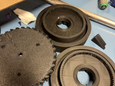
The majority of our fabrication process was completed through 3D printing. The freewheel device was ordered and assembled without any need of fabrication. The ratchet handles for the wheelchair hand drive were machined in the shop to reduce the diameter at the top of the handle to ensure that the break and rubber handle cover could be installed. The rest of the hand drive was 3D printed and assembled with basic hardware.
Testing Results
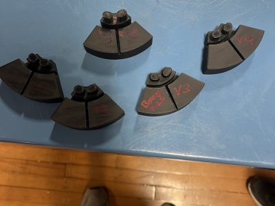
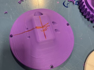
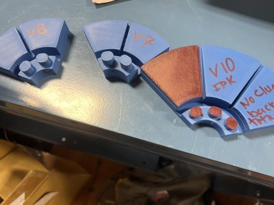
The testing process for the hand drive was thorough and involved lots of trial and error. To ensure that our hand drive would properly attach to the specific wheel on our student’s wheelchair, we slightly altered the open-source design to fit the desired specifications. We printed samples of the connection plate multiple times to ensure that the plate would fit snug onto the wheel once the full design was printed. Once the design was modified to our student’s specific wheel, we printed a prototype to ensure that all of the parts fit properly together. Once all of the final modifications were made, the final product was printed in PETG to ensure strength and durability.
Completed Design Photos
Instructions for Safe Use
After reviewing our design and assembly, there appear to be no major safety concerns. The following precautions should be made when operating the modified wheelchair:
Ensure that the wheel is on flat ground and stabilized before installing/uninstalling hand drive
Apply only reasonable force to the hand drive’s handles
Do not stand on the freewheel attachment or the wheelchair’s foot rests
Project Summary/Reflection
At the conclusion of our fabrication process, we delivered our two devices to our student at her elementary school. The freewheel attachment worked great, and we believe that it will be a great help to our student. The hand drive was able to be attached to the student’s wheelchair, but there is not much clearance to reach behind the wheel and attach the bracket to the inside of the wheel to stabilize the hand drive. Without this bracket, the hand drive can be easily removed with slight horizontal force, so this bracket must be attached with the hand drive. The current design does not facilitate easy installation/removal of the hand drive, which was requested by the school. If the student and family wish to keep the hand drive permanently attached to the wheelchair, then this design will be acceptable. If ease of installation and removal is a priority for the family, the design will need to be modified to accommodate this.
This project has been a great experience for all members of our group. We have worked well together to solve our given challenge and provide an innovative solution for our student. Our different backgrounds, experiences, and previous classes have prepared us well to complete this project. This project has all members of our group excited for what is to come in the remainder of our time as engineering students as well as our careers after graduation. It has been an exciting feeling to see the culmination of our hard work be able to impact another’s life for the better.