college of engineering white

Project 4: Hand-Crank Trike

Abstract

Our goal for this project is to build a hand-cranked trike for a child suffering from Spina Bifida, a condition that limits their leg mobility. We are prioritizing functionality and safety above all else while ensuring that the product’s use is an enjoyable experience.

Ryan Reed, Sydney Dukes, Robbie Hicks, Peyton Calitri

Design Specifications

The family has requested that the modified walker:

  • Can grow with the child
  • Includes safety features (such as derotation-strap supports)
  • Has a motor that can be turned on and off
  • Has a foldable step for the child to stand on


Corresponding Technical Requirements:

  • Build to last; the walker should be usable for years
  • Light and compactable; the walker should be light enough for a child to control, and should be easily stored
  • Safe; the walker should be able to meet the family’s requests while keeping their child safe
  • Power efficient; the walker’s motorized feature should be usable for a considerable distance and time before battery replacement or recharge. (Considering this will be used while the child is in school)

Concept Design 1

This design was based on the current walker that Paul had. We chose it because we thought that he was already acclimated to the design and it would be a natural fit for him. Based on how this walker collapses, adding the foldable steps on the sides will not inhibit the walker’s ability to fold.

Two battery cases will be supported by chassis attached to the legs of the front two wheels. There will also be extension features added to each leg of the walker.

Concept Design 2

This design was chosen because of the adjustable height capabilities. It allows the user to use his arms for support and greater stability while in motion.

Since the base of this walker is a hollow square frame, a foldable step and battery chassis can be placed in the frame such that the chassis do not inhibit the child’s movement.

Concept Design 3

This design is advantageous because of the compact storage option. It is also more affordable and an easier to modify design than Concept Designs 1 and 2. The lateral movement is easier to control with this design as well.

Battery chassis would only have to be installed on the back two wheels, and the handles can be modified to allow front wheel steering.

Overview of Selected Design

After a discussion with the mother of the child, it was decided that instead of building a motorized walker like another group, it would be more beneficial to build an arm-controlled trike. The purpose of the trike is to give the child a functional toy to ride along with his friends that doesn’t require force from the limited mobility in his legs. Trikes that avoid the use of leg power are not readily available on the market, especially ones fit for a 3-year-old child. Due to this change of path about halfway through our journey, we had to be efficient with our time and make quick decisions. Through a lot of discussion and research and planning, we came up with a design that will fit the child and his family’s desires perfectly while ensuring safety.

Describe Design Details

Our design involves using a foot-pedal powered, young-child sized trike that is readily available on the market and making a series of alterations to it. The base trike will come with rubber tires and a metal frame to promote comfort and durability. We will start by removing the handle bar from the trike and replacing it with a hollow tube from a beach cruiser bicycle. This tube will allow clearance from the fork for the chain, which we will discuss shortly. Attached to the tube will be a bottom bracket shell, which will hold a 3-piece bottom bracket. This bottom bracket will be in charge of holding the 1-piece BMX crank, which, when handles are attached, will act as the pedals that will control the movement of the bike. Also attached to this handle apparatus will be a small sprocket. The small sprocket will hold a chain that goes all the way down to the front wheel via a direct drive cog. The direct drive cog will be placed between the fork and the wheel. To ensure the chain is secure and to avoid any safety hazards, a majority of the chain’s path from the small sprocket will be covered. The direct drive cog will not only allow the foot pedals to move along with the arms (this was requested by the mother), it also prevents the need of a hand brake. The bike will stop whenever the hand pedaling stops. For the foot pedals, we will use ones that are heel-supported and velcro-strapped. This will keep the child’s feet in place during use. Lastly, we will apply a steering stop to the base that will limit the turn radius of the handles to protect the chains and provide easier control.

Engineering Analysis 1

This analysis focused on the reaction forces generated by the weight force on the seat.

Engineering Analysis 2

This analysis focused on the maximum moment that could be potentially generated by turning the handlebars.

Engineering Analysis 3

This analysis focused on the possibility that the ground pressure generated by the tricycle could be a potential concern for us.

CAD Drawings

Bill of Materials

Document Fabrication Process

  1. We first removed the stem from the base trike.
  2. We bought a donor bike from Goodwill, which we cut to isolate the bottom bracket crank and foot pedal system.
  3. We cut the foot pedals from the donor bike into handles. After using the belt sander and sand blaster to shape them into handles and remove the paint, we covered them with an air tight rubber sealant.
  4. In order to attach the crank system to the trike, we manufactured an adaptor out of aluminum using the lathe that fit the diameters of each piece. This new adapter would also behave as our chain tensioner down the road.
  5. We then cut the pedals off the trike to allow us to make alterations to the wheel.
  6. Next, we designed a piece in Solidworks that would allow us to attach a sprocket to the front wheel of the trike while also maintaining alignment for the chain.
  7. To get a chain to reach the wheel sprocket from the handle sprocket without interfering with any of the existing trike, we had to build an idler pulley that extends from the fork. This idler pulley was designed in Solidworks and was created in the water jet out of steel.
  8. Within the idler pulley is two scrap plastic sprockets that were donated from Caney Fork Cycles.
  9. To align the two sprockets with the one on the wheel and hand crank, we had to 3D print a spacer piece that would sit between the fork and the two metal pieces. The sprockets, sitting on bolts between the metal pieces, were aligned using various nuts and washers to fill space.
  10. Also, because the fork is at a slight angle, we bent and twisted the metal plates to match the vertical alignment of the chain.
  11. There was a structural bar wrapped around the front of the trike to under the seat of the trike for support, but it would interfere with the chain path, so we welded a steel bar under the seat to make up for the lost integrity and cut off and sanded down the original bar.
  12. We then went to Caney Fork Cycles to get fitted for a chain. The chain was tensioned via the adapter (we could raise and lower it accordingly).
  13. Next, we designed a 2-piece chain cover in Solidworks that we would bolt into the stem. This protects the chain attached to the sprocket on the hand cranks.
  14. To guard the rest of the chain, we cut a piece of acrylic and bolted it onto the outside idler pulley plate and then glued it to the outside of the chain cover. This eliminates any risk of the child touching the chain while in use.
  15. We then attached a seatbelt to the wooden platform on the back of the trick via bolts that were already made. One side was sitting awkwardly, so we manufactured a piece out of metal to act as a 90 degree bracket. That seatbelt piece was bolted to this to allow more comfortable use.
  16. Next, we designed 2 pedals in Solidworks that we 3D printed. These pedals sat on 2 platforms that we also designed in Solidworks and made out of aluminum that attached to the fork via existing holes and special bolts that we ordered.
  17. The pedal design allowed us to thread a piece of velcro through each of them to allow the child to strap his feet in.
  18. We then designed 2 stickers that would be placed on the trike: one on the seat and one on the connection between the fork and the stem (the sticker covered the grinding we did to remove a weld).
  19. Lastly, we painted all parts of the trike that were either grinded or from the red donor bike.

Completed Design Photos

Instructions for Safe Use

The trike was built to be as easy and safe to use as possible. Some of the safety features include a seatbelt, pedal straps, heel support, and chain guard. While none of these things were necessary for the functionality of the trike, they assure that the child will be able to ride without being at risk of injury. Beyond this, it is just recommended that the trike not be used on steep hills; the trike uses a direct drive system, so if the trike were to begin rolling at a high speed down a hill, it would take extra force to maintain control of the hand-cranks.

Project Summary/Reflection

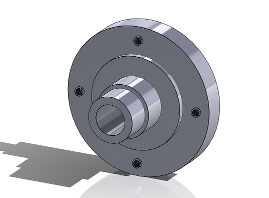
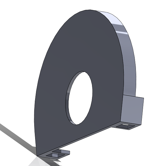
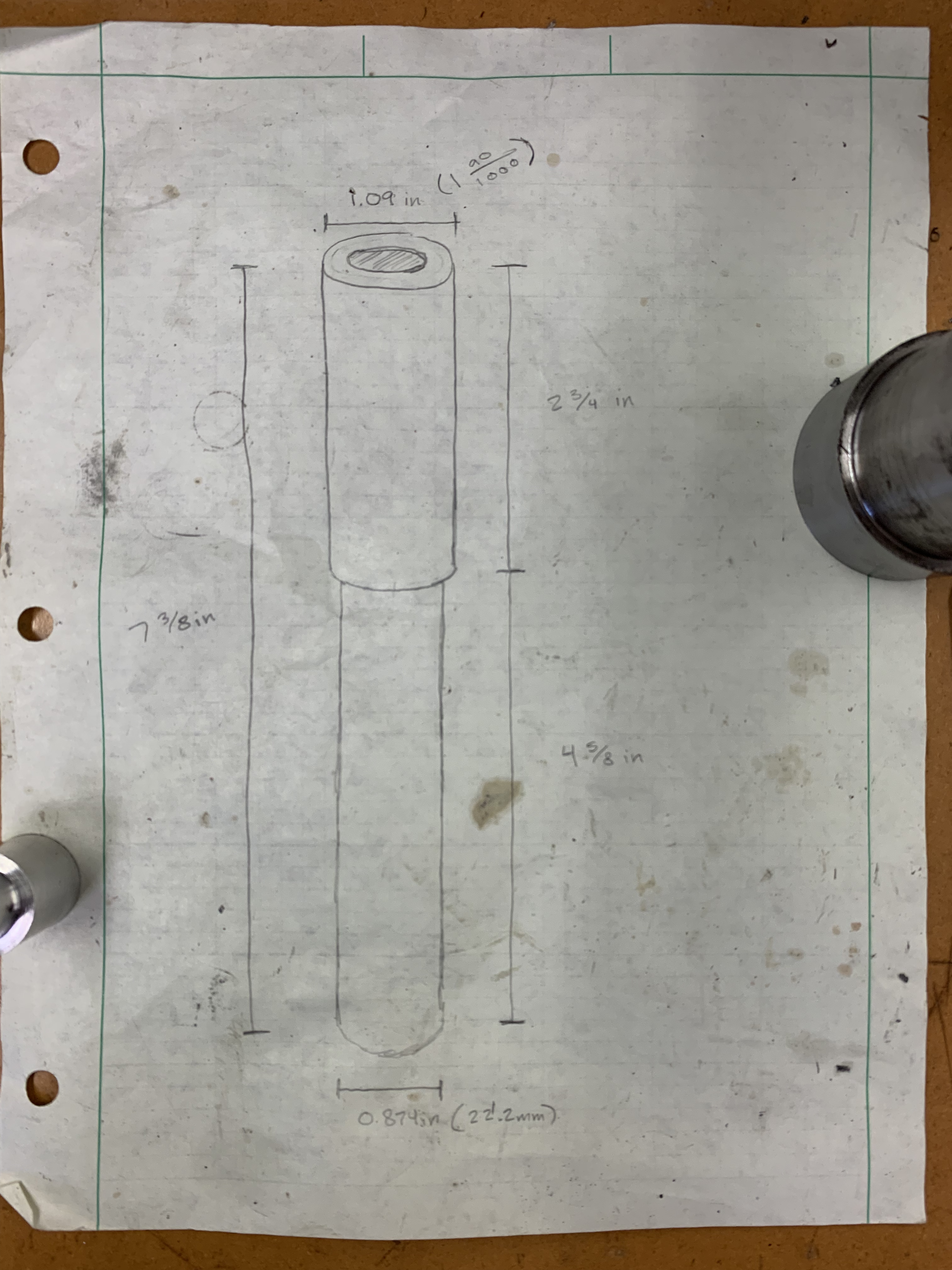
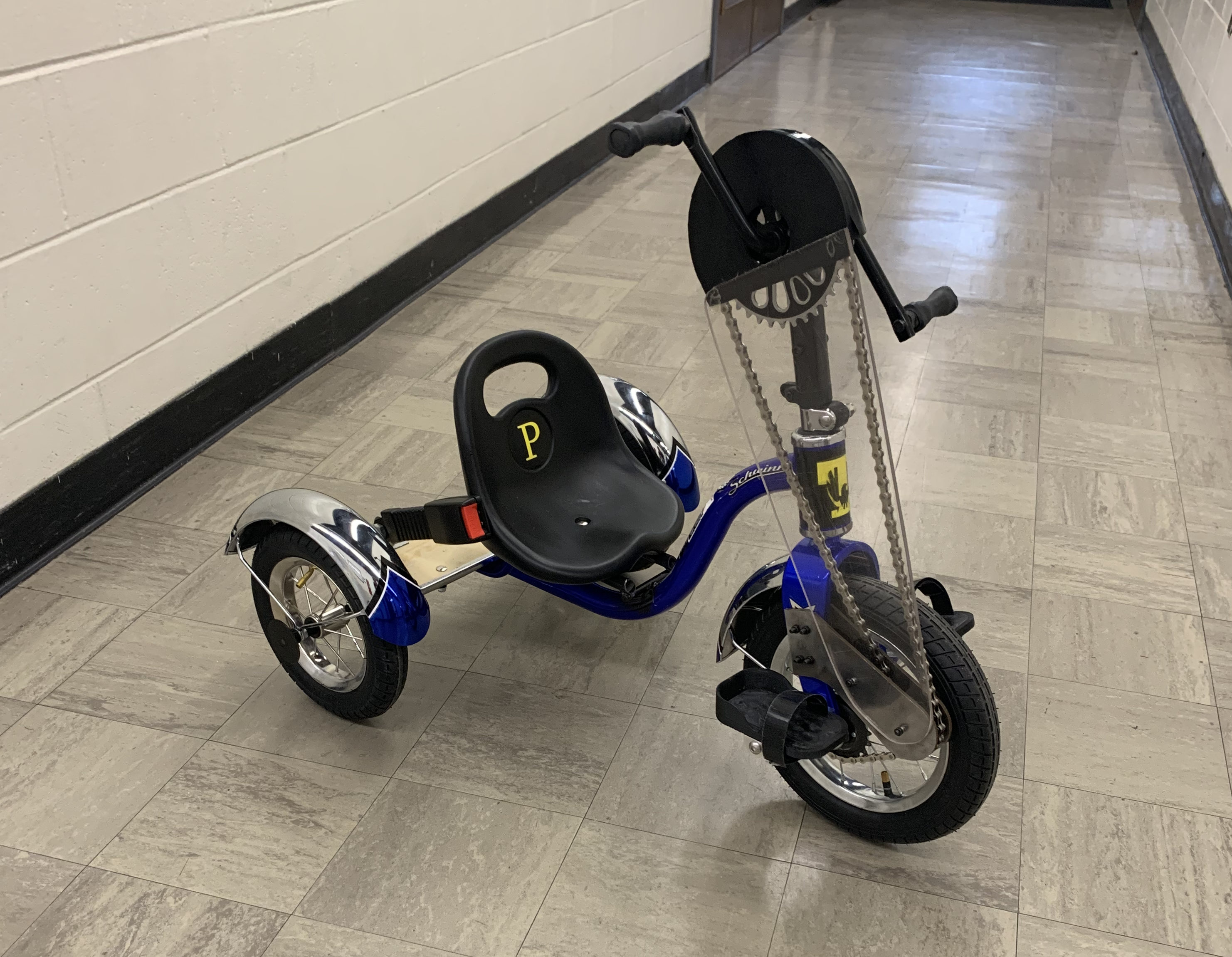
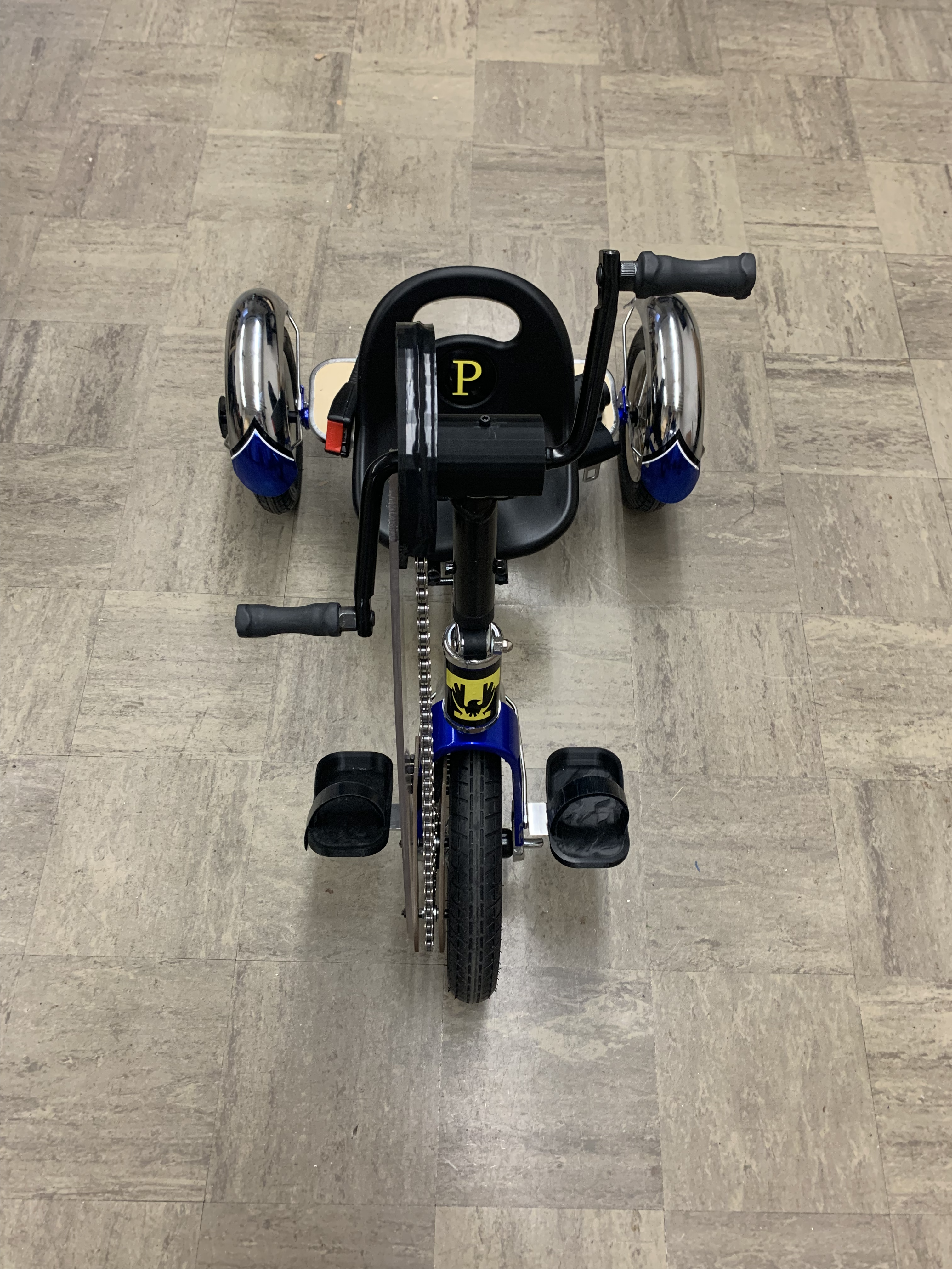
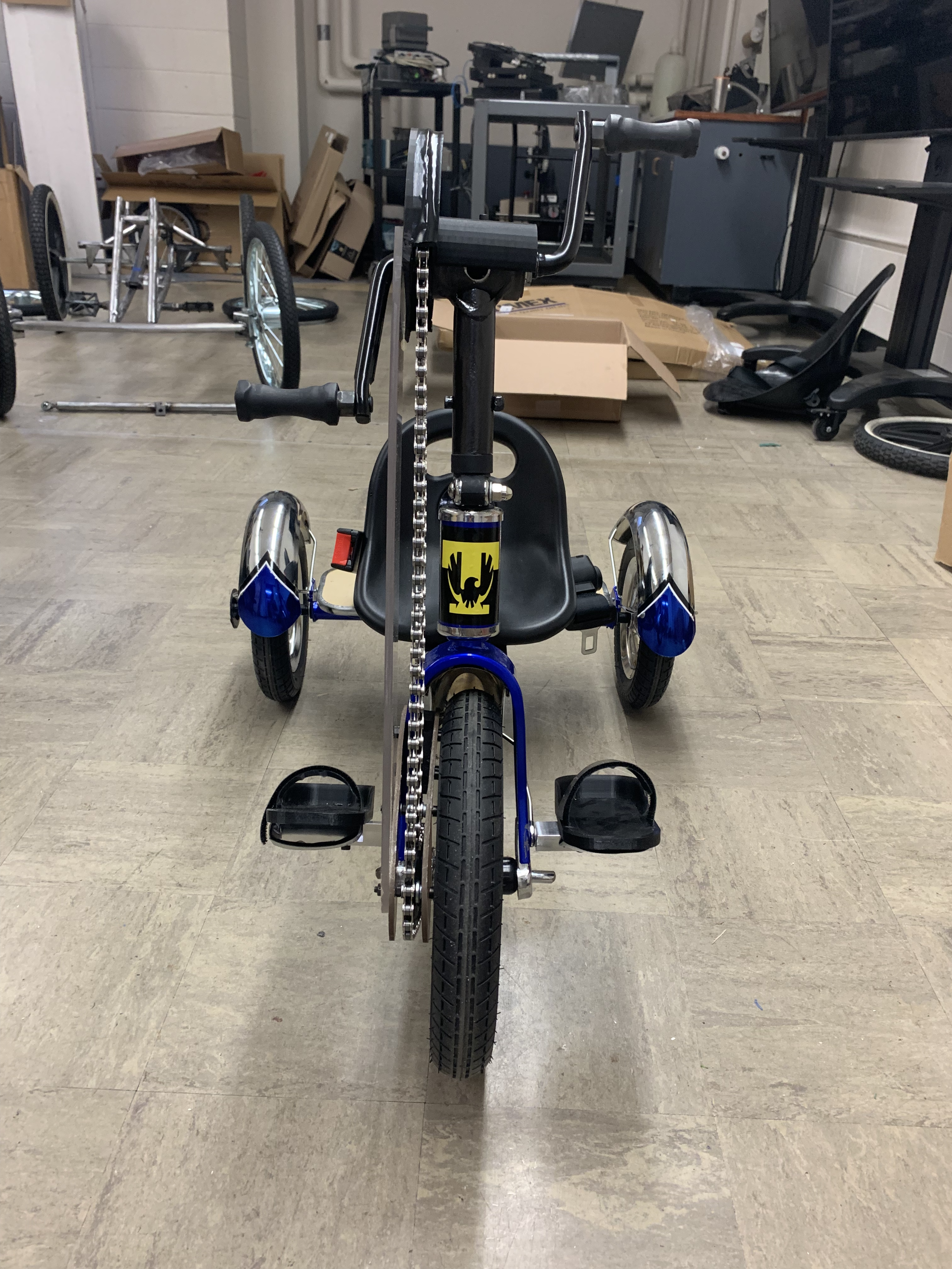
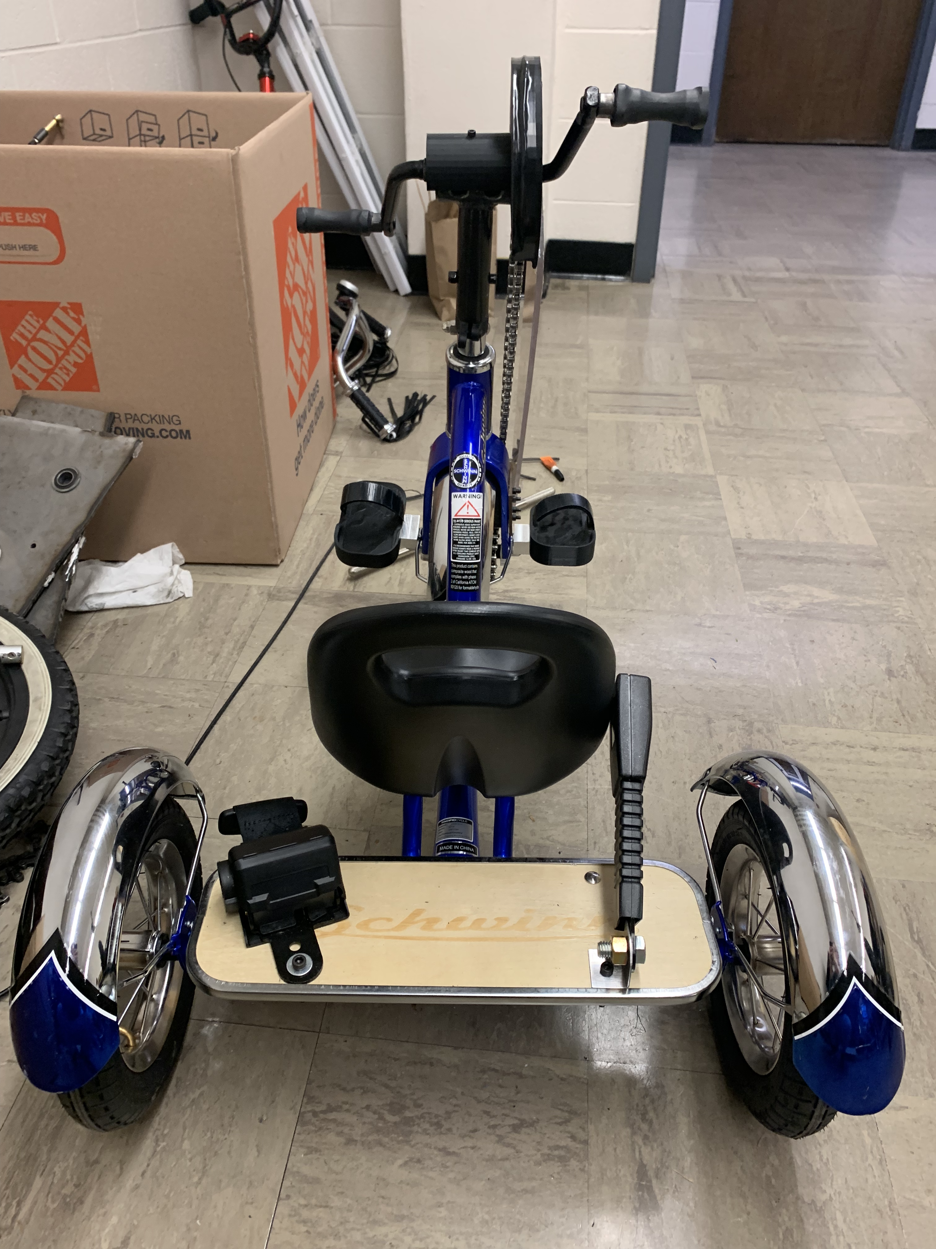
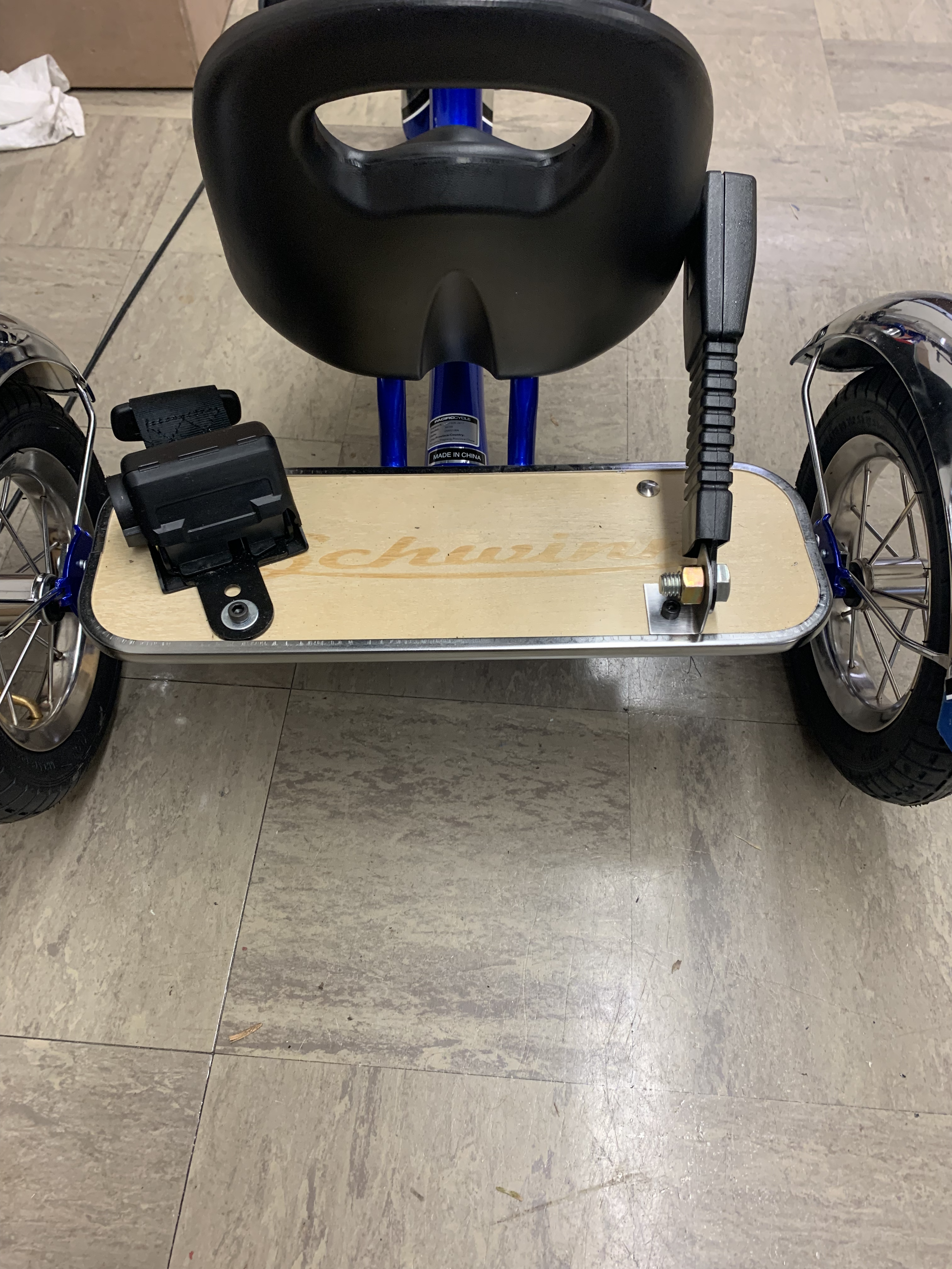
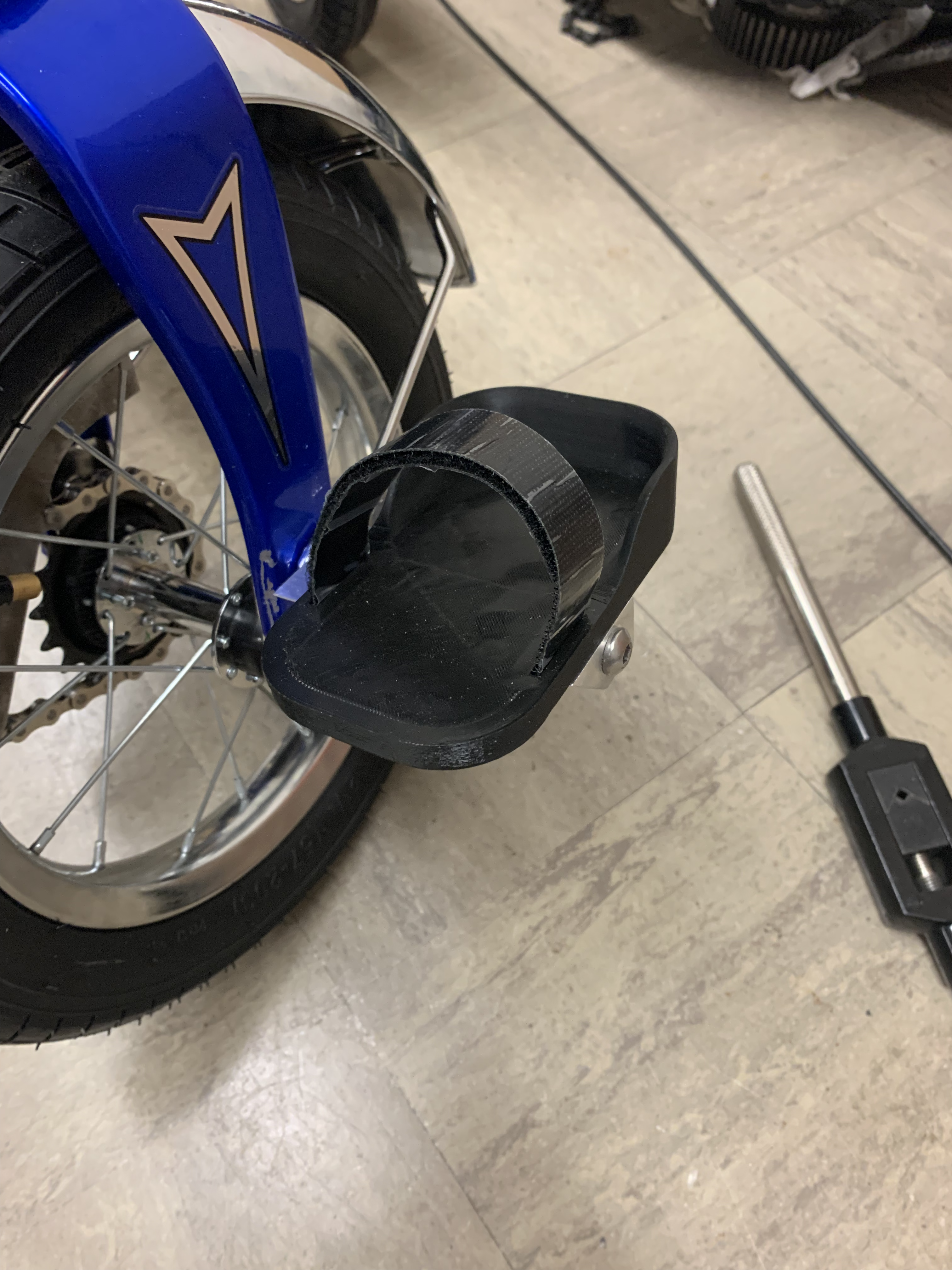
This project was a major learning experience for our group. While we were able to accomplish what we set out to do in our original design, we achieved it in a much different way than anticipated. Despite us planning on buying everything that would be put on the trike, we ended up only purchasing the base trike, some bolts, a seat belt, a new chain, and an $8 donor bike from Goodwill. Instead of buying more, we designed and fabricated 13 parts out of metal, plastic, and acrylic through CAD/drawings that were implemented on the final design (we made a lot of parts that were not ultimately used). This was way more than our original plan of zero.

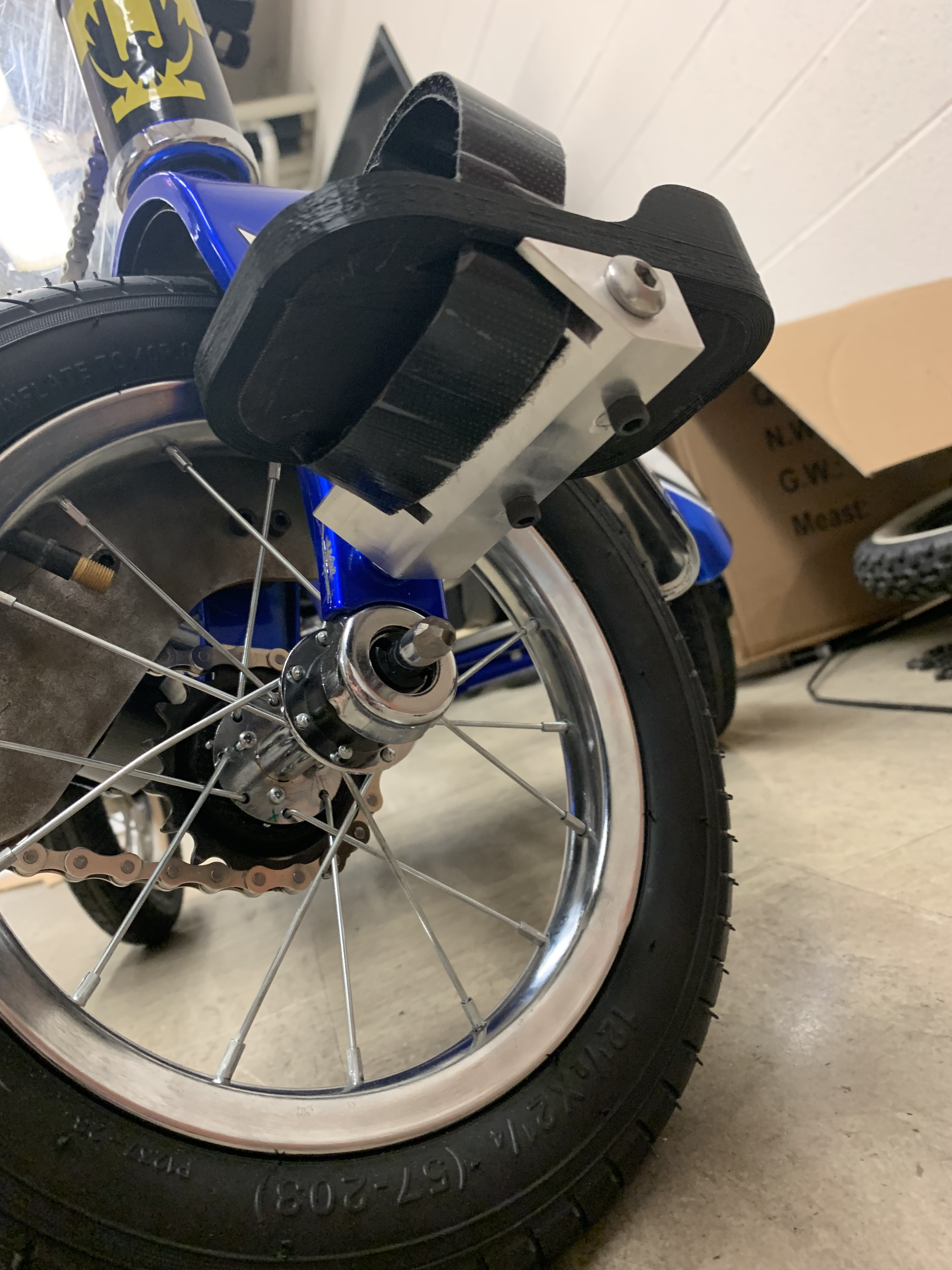
Overall, we were able to put a lot of the machines and tools in the shop to use throughout this project. These include a mill, lathe, drill press, belt sander, band saw, water jet, dremel, and many more. Being able to use a lot of these machines opened our eyes to the importance of designing to manufacturability. While these tools can do amazing things, there are so many things that are needed to be accounted for to make sure parts are made successfully. Whether it’s the placement of dimensions on a drawing, the size and lengths of bolts that are common/readily available, or the fact that bolt head dimensions are necessary in conjunction with the rest of a design, the only way to learn is to experience first hand.

We also learned how difficult it is to alter a manufactured product that isn’t designed to accommodate major changes. Because of this, we found ourselves building and adjusting parts without worrying about future creations. This method took a lot of time, but it left us with a better understanding of our trike than if we had taken a different route. If we were to redo the project with the knowledge that we have now, it would probably take us a week to complete instead of a few months.

Ultimately, this project was an incredible learning experience for all of us. It would be wrong of us not to mention the help we received from the guys at Caney Fork Cycles. We would check in with them regularly throughout the project to get advice on our design, and that helped immensely. We also couldn’t have done anything without the assistance and mentorship of Chris and Jeff in the machine shop. They taught us so much throughout the project and we would not have gotten as far as we did without them.

Semester

2022 Fall