


The First engineering analysis pertains to the loading the motor will see. We wanted to determine the torque, power, and current the motor would see when it was subjected to the applied loads to determine the required motor and battery size. The applied loads are the weight of the food, weight of the actuator, and force of the spring.
Assumptions:
The load directions and locations are constant.
The drawer slides apply no friction.
The motor rotates at a constant velocity.
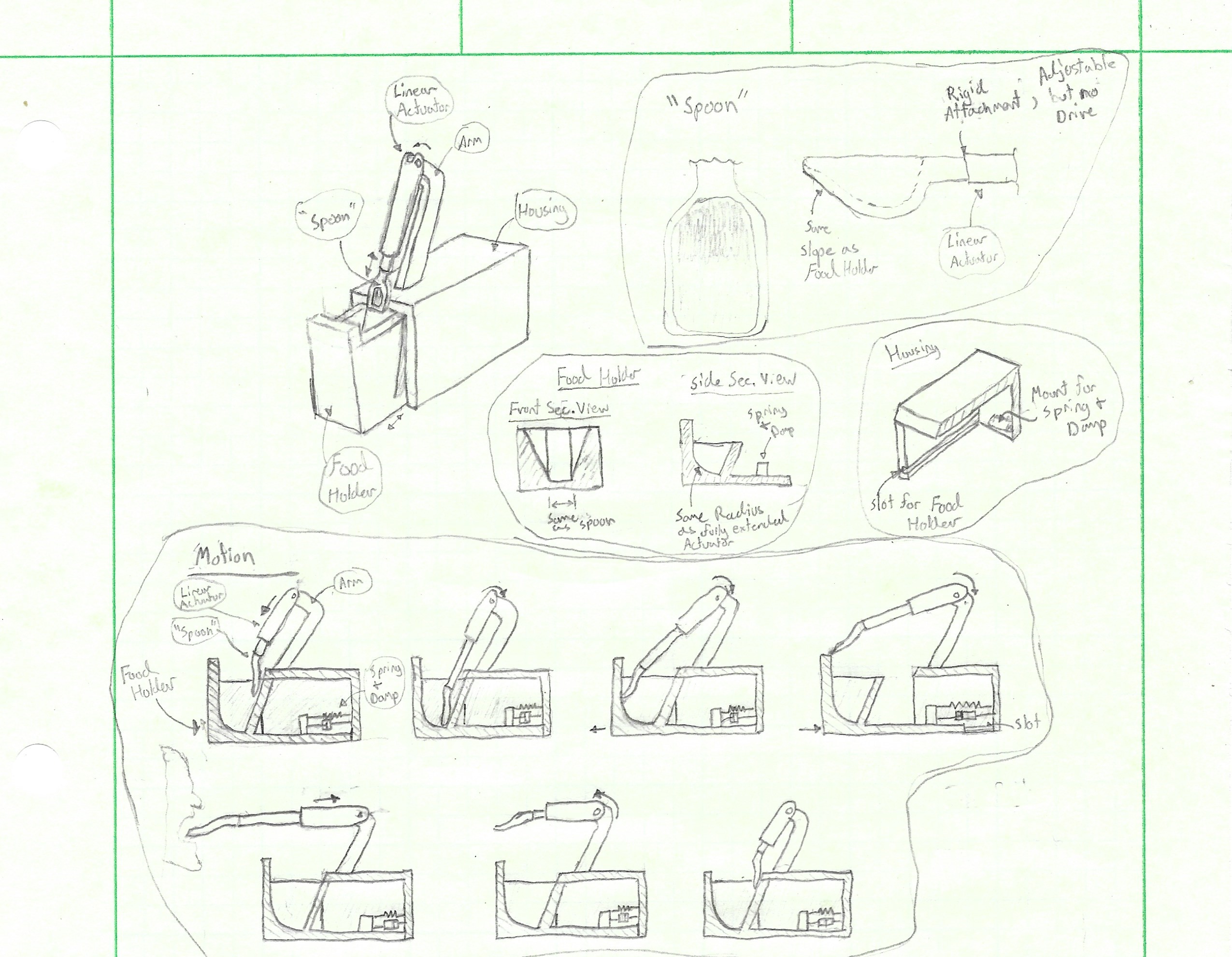
With these assumptions in mind, we derived equations for the torque and power on the motor would need using static equilibrium shown in the figures below.


Arriving at the equations

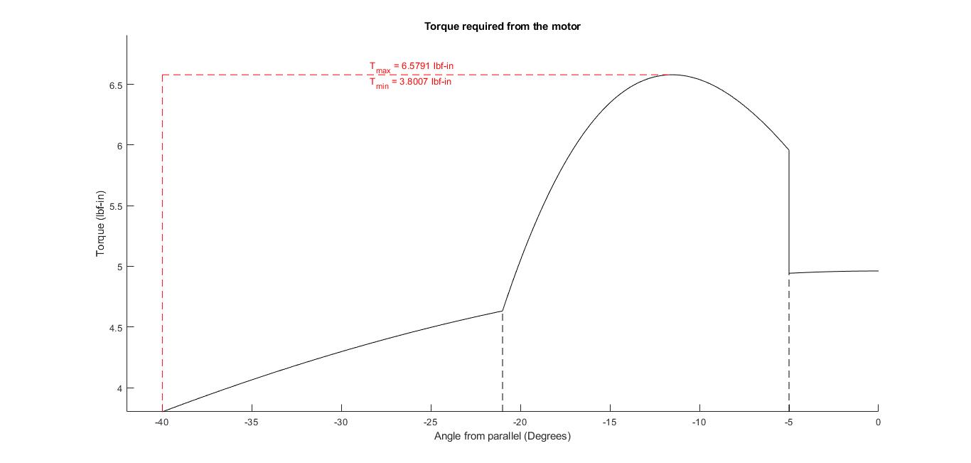
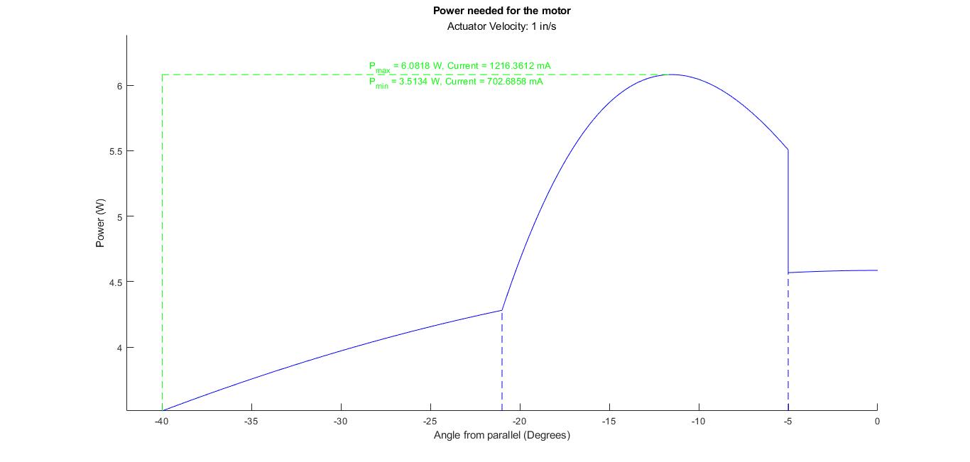
Once the equations were derived, we wrote a MATLAB script to make calculations and plot the results shown in the figures to the right.
Our calculations show that the motor would see a maximum torque of 6.5 in-lbf or 7.5 kg-cm. The maximum power required to drive the 5v motor at 1 in/s would be 6 W with a current draw of 1200 mA. This tells us that a 10 kg servo should be able to handle the applied loads and a LiFePO4 7Ah Battery would be sufficient to supply it.
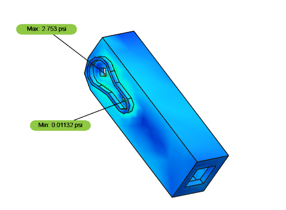
The Second Engineering analysis is with respect to the loads seen by the linear actuator. We wanted to determine the axial and perpendicular loads on the actuator to make sure they did not exceed the limits. The manufacturer rates the PA-07 for a static axial load of 6.5 lbf. With the same assumptions made as in the first engineering analysis, we derived equations for the axial and perpendicular loads on the actuator shown in the figure below.


Arriving at the equations

We calculated the results with the same MATLAB script shown to the right. Our calculations show the maximum axial force on the actuator as 0.622 lbf and the maximum perpendicular load as -0.514 lbf. These loads are well within the limits of the manufacturer’s rating. The actuator draws 100 mA with no load. The 0.622 lbf would increase this current to 124.4 mA.


Before we began building the housing and food holder, we wanted to make sure that we could control the servo and actuator.
The first two images show the servo being controlled with a normally open button, arduino, and power supply.

Servo in Neutral Position

Servo Bottom Position
We then wrote a script to control the actuator using a relay, power supply, and an Arduino. Shown in the following images.

Actuator Circuit

Extended Actuator

Retracted Actuator
We then wrote a script to control the actuator and servo at the same time, and power them both with a battery.

Actuator and Servo rest position

Actuator and Servo end position
After we knew our code could work, we built the food holder, housing, and support arm. Some changes were made to the housing to make it easier to assemble. We added in rectangular slots to the housing panels so they would fit together. We also changed the support into a rectangular tower that would hold the servo and actuator.

Food Holder.

Housing being glued together.

Housing and Food holder assembled.

Circuit to be built.

Tower and Circuit being constructed.

Circuit mounted inside housing.

Full Assembly
After the assembly was completed, we noticed that the spring we had chosen too strong for our application once friction was involved.

Spring connecting food holder and housing.
We replaced the spring with a much weaker rubber band, and it seemed to fix the issue.

Rubber Band connecting food holder and housing.
We then made sure our Voltage regulator was outputting 5V as intended.

Voltage Meter testing the output from Voltage regulator.

5V output
We then began the first test run of our assembly. Upon plugging in the battery, the servo went to the wrong position. It went to roughly 45° above parallel instead of 40° below parallel. When we pressed the button, it traveled to roughly 85° above parallel instead of parallel.

Servo 45° above parallel

Servo 85° above parallel.
We altered the code, and the servo began working as intended. However, the servo could not make it through the full range of motion due to the spoon getting stuck on the bottom and back of the food holder. The servo would start stuttering while trying to reach the 40° position requiring us to elevate the actuator.
We chose a strong servo because we knew that this could be an issue, but it seems like either the servo is not getting enough current or that it is getting caught. We believe that it is getting caught. Future revisions could use different materials to greatly reduce the friction but for now, we reduced the friction by removing rough spots and increasing the speed the servo traveled through the holder. This seemed to mostly fix our issue.
The first successful run showed some flaws in our spoon’s design. The side walls of the spoon are too shallow to contain some foods and the spoon itself is not deep enough. Future designs should account for this.


