Spring 2026 Project 14: Sensory Toy 2 for High School
Abstract
This project develops a themed sensory board with interactive panels designed to promote independence and sensory engagement in the Upperman High School sensory room.
(Left to Right): George Songers, Nick Romsdal, Eric Tran, Kylie Truong
Problem Statement
This is one of the sensory boards that will be incorporated into the sensory room for Upperman High School. Its primary purpose is to promote user independence by providing accessible sensory activities that support self-regulation, motor skills development, and problem solving. The board itself includes a multitude of sensory interactions that students can choose from, including tactile surfaces, moveable objects, and components that provide auditory or visual feedback. The main issue is that the design requires batteries and electrical circuits. The components need to be protected so that students can’t tamper with them but remain accessible for teachers to perform maintenance. The final design must be interactive, safe, and structurally secure, while also incorporating an Avatar-themed design that fits within the sensory room environment.
Design Specifications
Frame
L x W x H: 30 in x 3.75 in x 50 in
Wall mounted to a CMU wall using 3/8 masonry anchors to prevent tipping
Held up by vertical support pillars to further help stabilization
Panels
12 in x 12 in
Electrical components (batteries and circuits) must be enclosed to prevent student access while allowing teachers to perform maintenance
All panels and individual components on the panel must be mounted securely so that they can’t be easily removed/broken from normal use
Other Specifications
Materials must be durable and safe to withstand repeated use
Overall design should align with Avatar theme
Background Research
When researching tools and mechanisms to stimulate auditory senses, the team kept an open mind in including strictly physical audio sources as well as electrical audio sources. The physical audio sources include gurios (shown right), xylaphones, and bells.
To further enrich the students’ senses, the team employed resident electrical engineering (EE) experience to incorporate electrical circuitry. Incorporating EE knowledge expanded background research to include lighting, slow motion, and sound effects.
Concept Design 1
The team considered installing the boards on a slider rail inspired by the other sensory board attached to this project. This design is optimal for maintainability in the form of replacing the batteries by sliding the boards out and swapping batteries. This feature can also be considered a risk, as the students could just as easily remove the boards from the stand and play with the wiring, leading to potential low voltage danger.
Concept Design 2
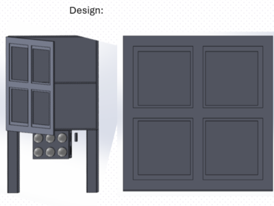
To resolve the issues found in the inital concept design, the team looked towards partially encasing the boards behind a door (Reference image shown right). The door would consist of a frame to still allow the students to enjoy the boards while not being able to play with the electrical wiring. For maintaining the boards long after the product is installed, the teacher(s) can open the door and swap out batteries.
Concept Design 3
Within the first few days of reaching out to the customer, the team thought of permanently installing the boards to the wall. While this option maximizes the safety of the student(s) using the product by not exposing the wiring at any point, it also prohibts the teacher(s) from maintaining the boards by replacing the batteries. The use of a wall outlet power supply was considered, however the team elected to minimze the number of wall outlets used in the project to minimize the risk of being unplugged by the student(s).
Selected Concept Design
As shown in the decision matrix, the team elected to further develop conceptual design 2. This concept allowed for a balance between servicability by teacher(s) in replacing batteries and safety for the students to not accidentally handle electrical wiring.
Decision Matrix
Overview of Selected Design
Panels:
Designs on individual slabs that will be mounted to the main cabinet
Cut out on the cabinet front panel so that the back of each panel is accessible inside the cabinet
Doors:
Cabinet design allows hidden access to the circuitry behind each slab
This stops students from yanking at any wiring
This allows teachers to change batteries without it being out in the open
Misc:
Will be raised in the air with some pillars
Mounted in the wall to prevent any tipping from happening
All the plywood will be colored and sealed
Describe Design Details
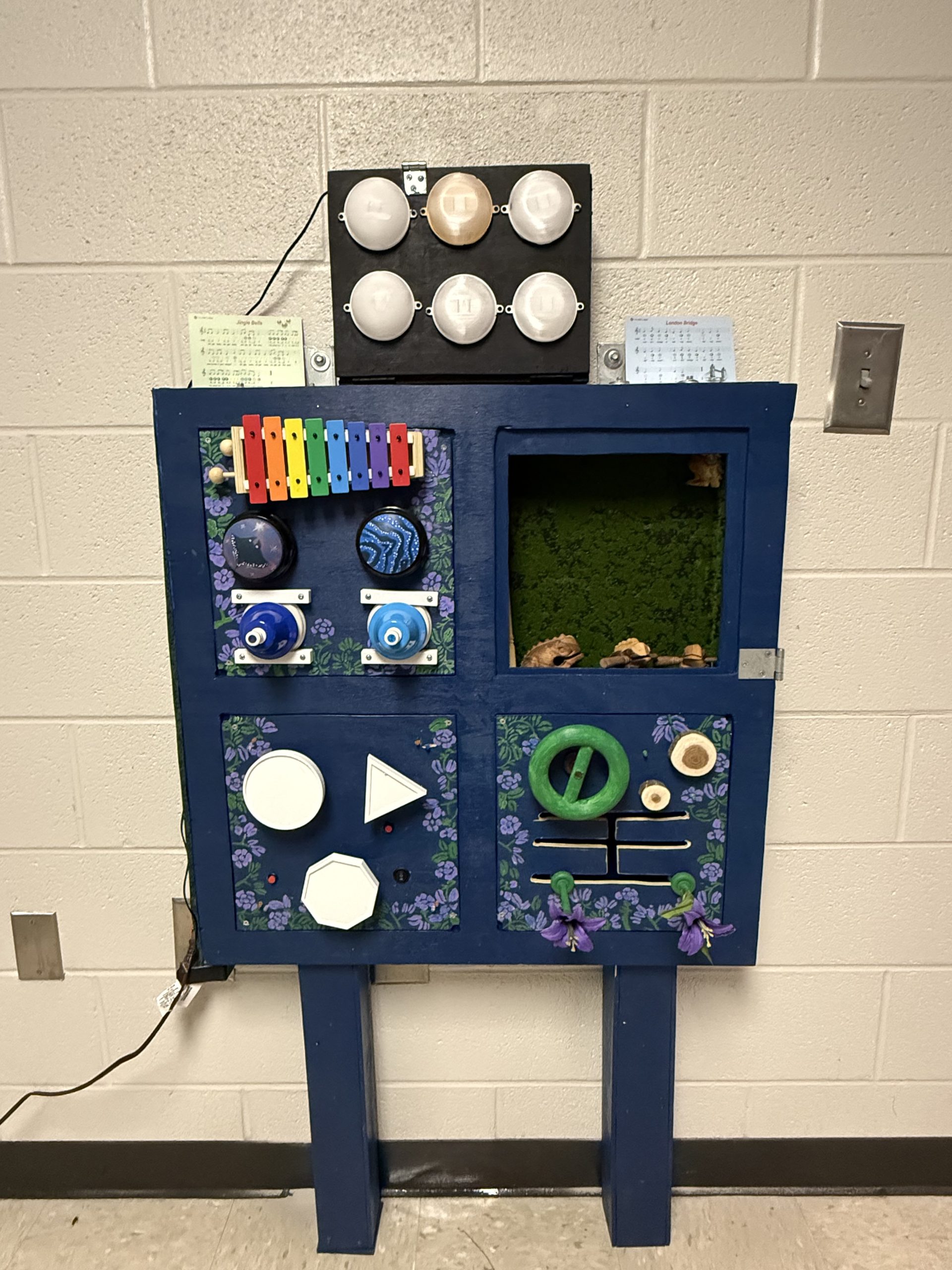
The sensory board will consist of 12-inch by 12-inch interchangeable panels. Each panel is designed to provide a different type of sensory interaction to encourage engagement, motor skill development, and independent exploration.
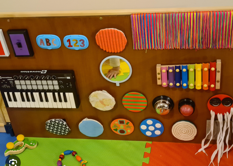
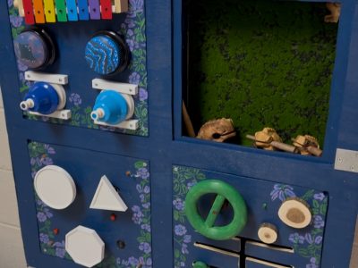
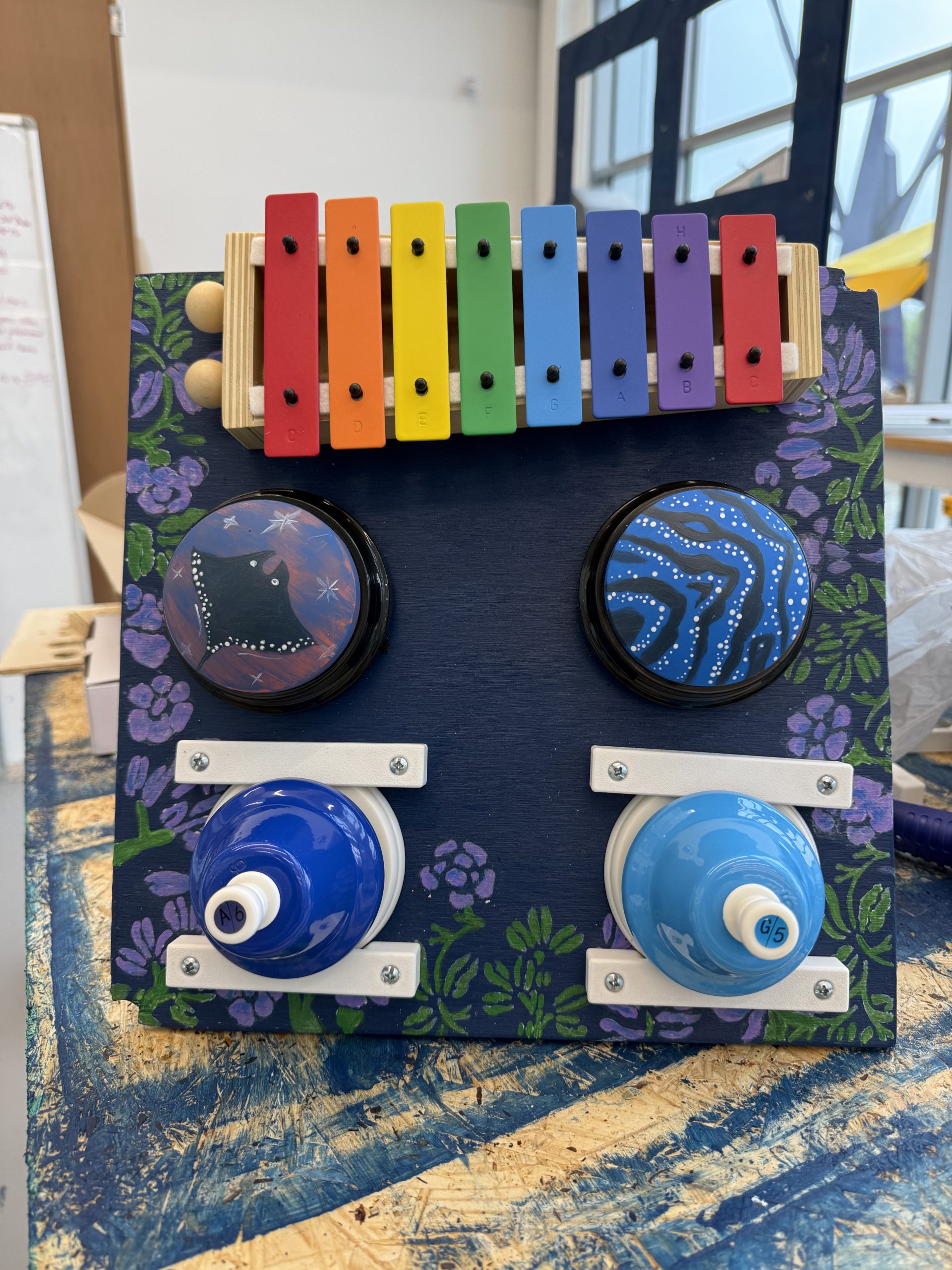
Panels 1 are auditory sensory boards. Panel 1 includes a xylophone, bells with different tones, and sound-recording buzzers that will play calming nature or animal sounds inspired by the Avatar movie. These components provide auditory feedback while also encouraging students to interact with the board.
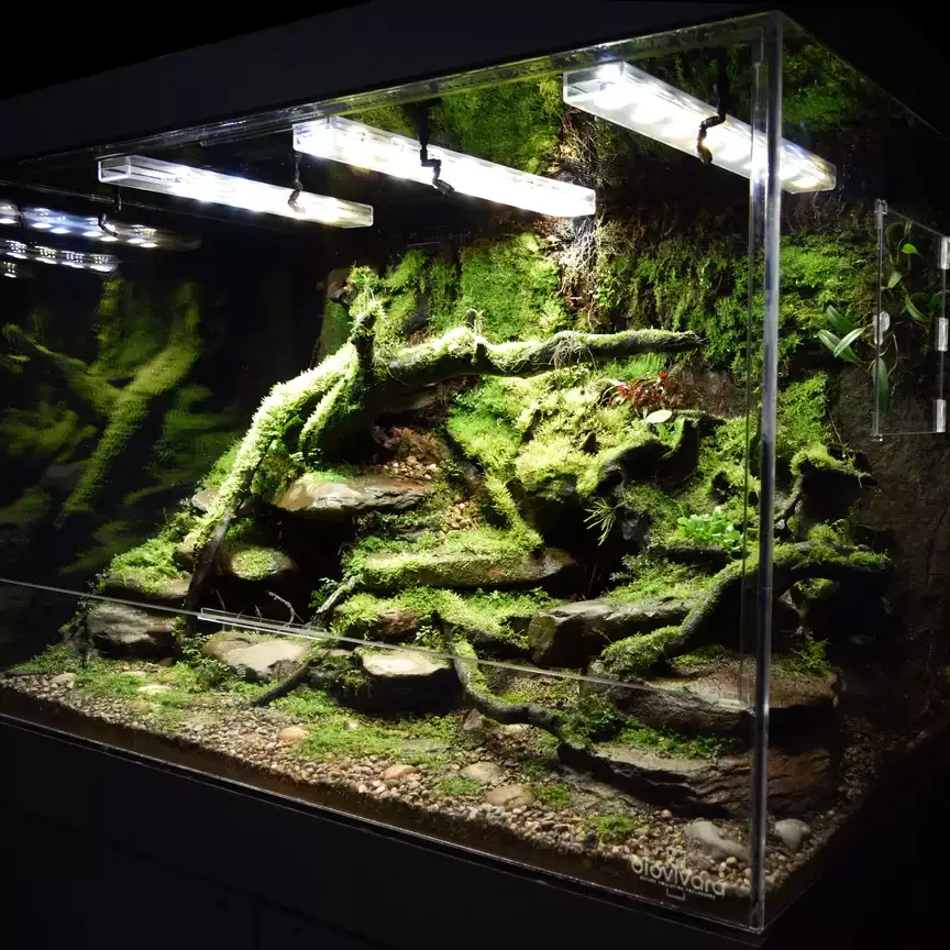
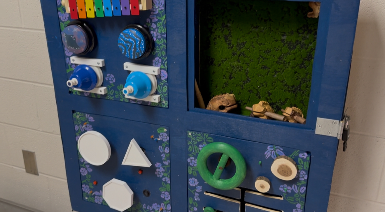
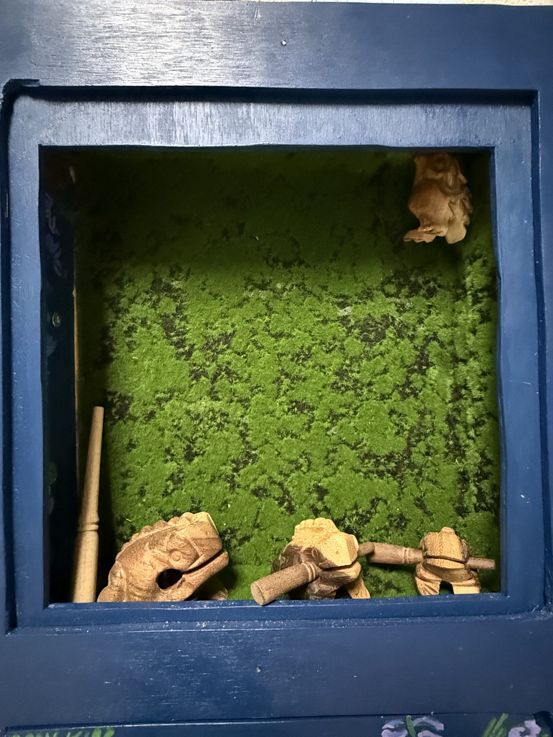
Panel 2 is a replica of of frog enclosure. This compartment is enclosed by internal shelves so that students cannot access the circuitry or electrical components. Inside this section is a moss rug and a guiro frog instrument that students can touch and play with.
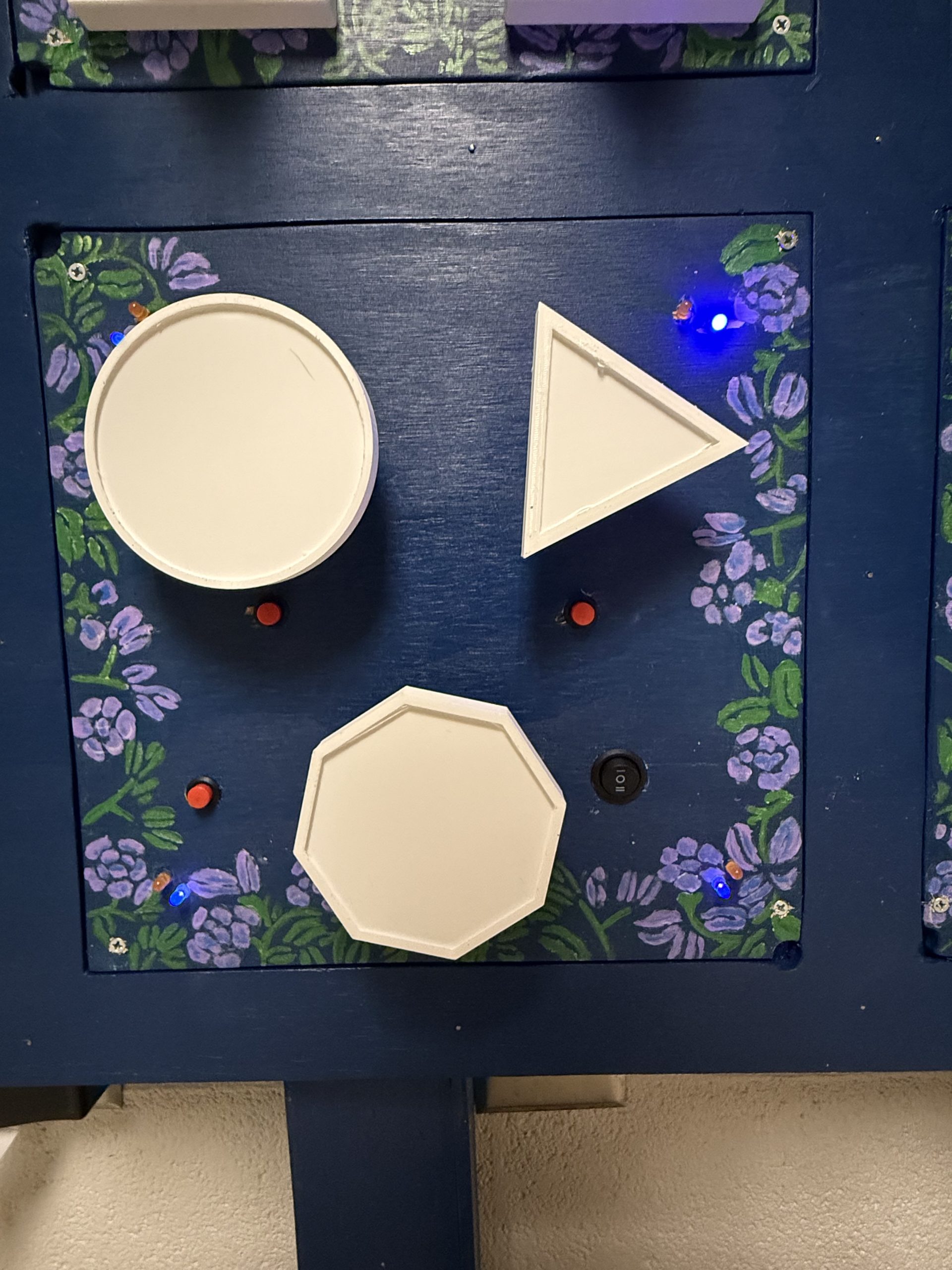
Panels 3 and 4 focus on visual sensory stimulation. Panel 3 has a wildlife theme and includes three shapes powered by motors that will rotate when its respective buttons are held. These shapes can have images attached to them. There are also LEDs tied all around the board with a switch controlling whether they are a shade of orange for a “daytime” orange hue or a shade of blue for a “nighttime” purple/blue hue.
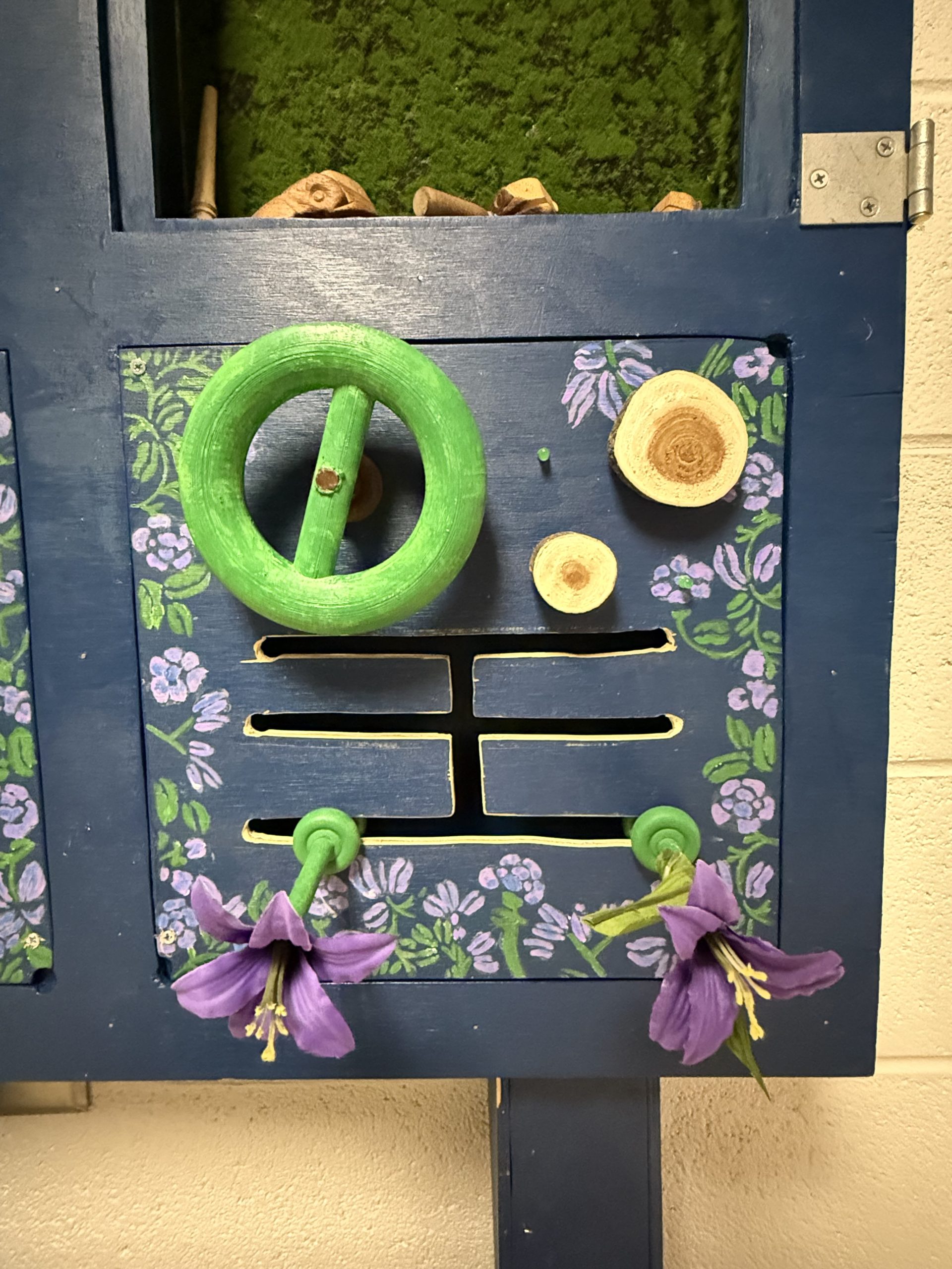
Panel 4 has a tree theme and includes a rotating wheel that students can interact with. It also has two push-in blocks with a wooden texture that, when pushed in, causes an LED to turn on. There is also a movable rod path that students will be able to move around, decorated as a flower.
Each panel is securely mounted to the frame and designed to withstand repeated use. The components are attached using fasteners or embedded mounts to prevent removal during normal interaction. Additionally, panels containing electronic components have enclosed compartments to prevent student access while still allowing teachers to perform maintenance when necessary. The overall aesthetic of the panels follows the Avatar theme used throughout the sensory room.
Engineering Analysis 1
To find the tipping moment we first had to find all the forces acting on the board. The forces acting on the board are the weight of the board and the horizontal pulling force at the highest point of the board. This force is to act as someone pulling on the board, causing a tipping moment.
The conclusion from this calculation is to mount the board to the wall to prevent tipping, since it is really easy to tip over plywood boards.
Engineering Analysis 2
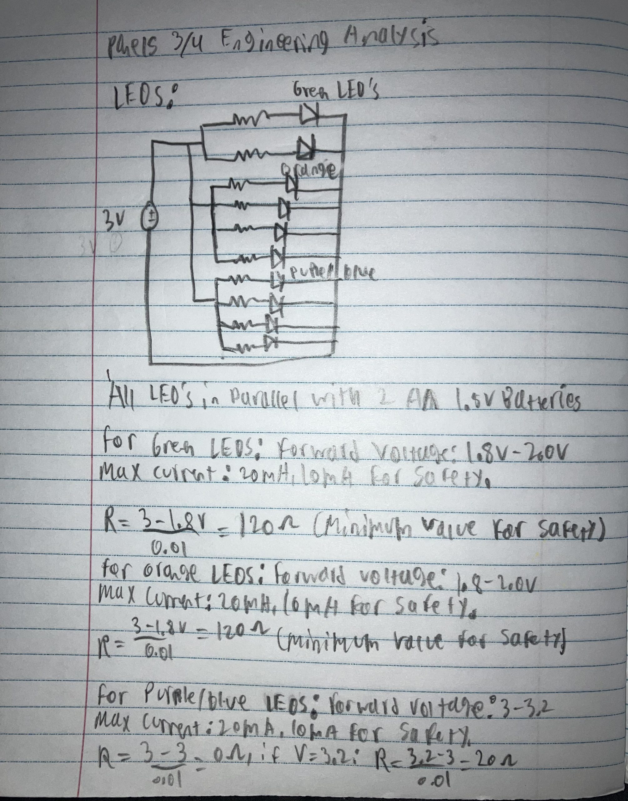
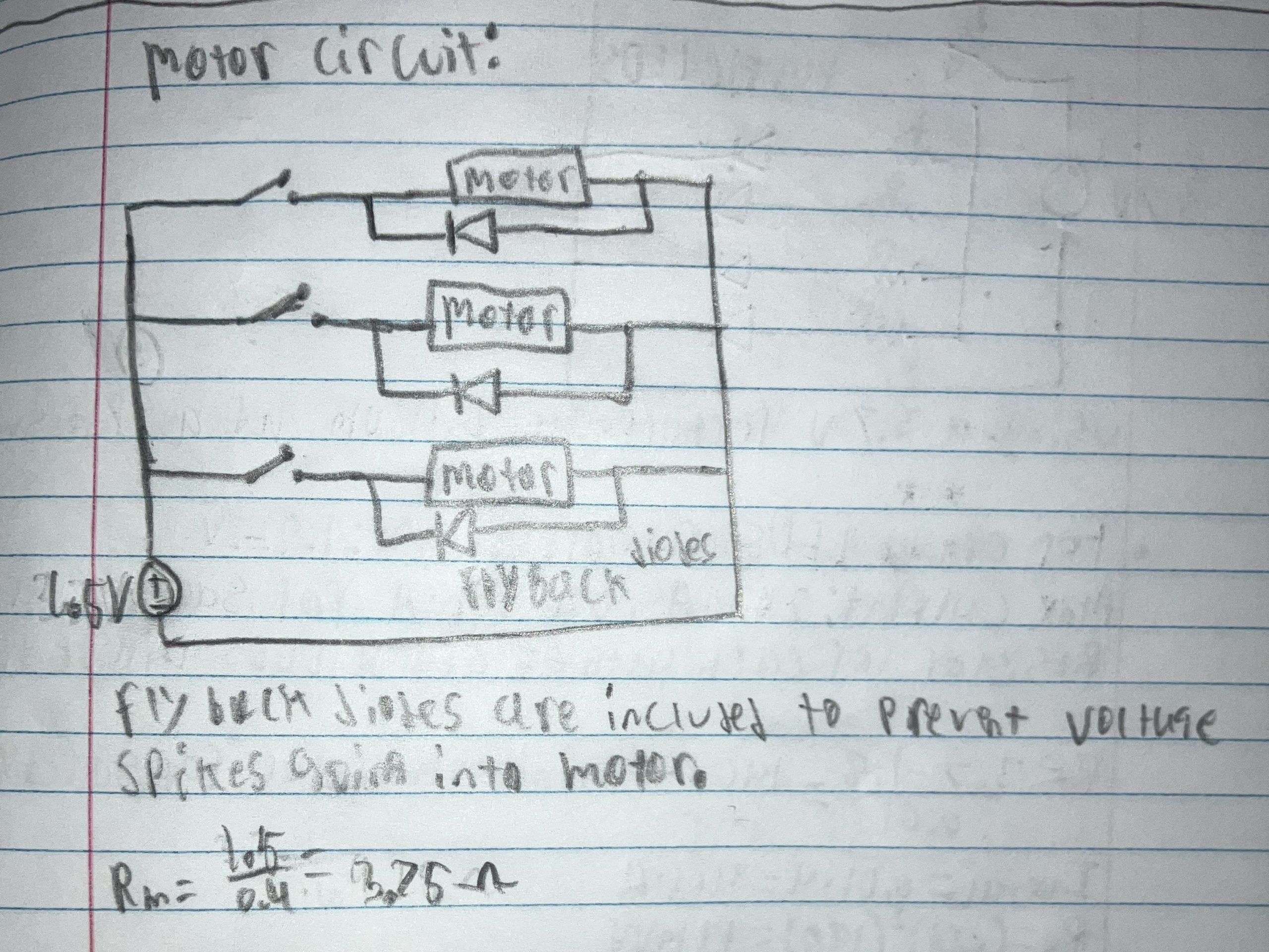
To ensure that the current going through the LEDs of the third board does not go beyond the maximum current, a circuit analysis was conducted. By using a 3V voltage source, the forward voltage of both the orange and blue LEDs, and the maximum current of 20mA of the LEDs, the minimum value for the resistors could be found. The resistance for the motors was also found.
The conclusion from these calculations was that for the orange and green LEDs, the resistors need a minimum resistance of 120 Ohms, and the blue LED circuit needs a minimum resistor value of 20 Ohms. It was found that the motors need 3.75 Ohms of resistance.
Engineering Analysis 3
Engineering analysis 3, shows how much current is needed to power all the LEDs and speakers, and if the Raspberry Pi and power supply can handle it all. Knowing the forward voltage of the LEDs I will be using and the amplifier used for the speakers, I can calculate total current needed throughout the whole circuit.
The conclusion from these calculations was that I will need to 220 ohm resistors for the LEDs and to power the amplifiers through the 5V pin on the Pi. The total current needed is around 2.5A, which if powered correctly, should all work.
CAD Drawings
Bill of Materials
Document Fabrication Process
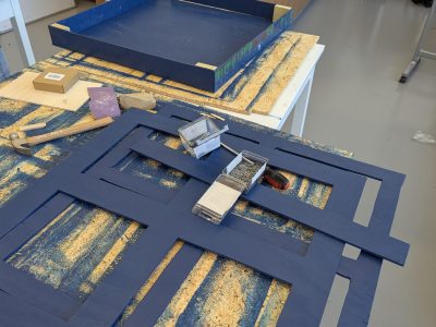
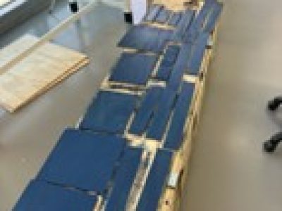
The construction process began with sectioning, cutting, and staining all necessary plywood with a pre-stain and blue stain finish. Once the pieces were ready, the cabinet was assembled by nailing the front door panels together, attaching the walls to the back piece, adding support blocks for the hinges, and installing interior dividers to separate the four panels when closed. All panels were then painted with flowers and vines to follow a nature theme.
Each panel was designed with a specific sensory focus. Panel 1 features Avatar-themed buzzers velcroed to the board for easy removal and battery changes, along with a xylophone and bells drilled into the board with 3D printed supports. Panel 2 was lined with a moss rug and incorporated guiro frogs, with one drilled in and two left free for students to carry around. Panels 3 and 4 utilized 3D printed components, motors, spinning shapes, latching buttons, switches, and LEDs, with all wiring and soldering completed on the back of the panels and battery packs secured in the most convenient locations.
The construction of the button board began with assembling a plywood enclosure to house the wiring, and the Raspberry Pi used. Once the enclosure was prepared, both the button holder and dome were 3D printed. The dome was produced with clear filament to ensure visibility of the LED. The button holder was designed with slots to securely position both the button and LED components. The system’s functionality was driven by code implemented on the Raspberry Pi, which was configured to manage all LED outputs and speaker controls. This allowed for physical button inputs and the corresponding visual and audio feedback, completing the overall design of the button board system.
Testing Results
The cabinet door was tested to ensure that the door would open properly. Regarding the individual boards, each board was toyed with to make sure that things wouldn’t break easily and thateach piece functioned as designed.Once the legs were added, the cabinet was standing up to ensure the legs could hold the weight of the cabinet and not tip over. In conclusion, the testing process for the board went well.
Completed Design Photos
Instructions for Safe Use
Keep the door locked to ensure that students do not mess with inner wiring.
Do not jump, climb, or pull on the board.
Parts are to be used as intended. Excessive force can break the individual parts.
Extra Useful Instructions
Panel 1 – Each buzzer requires 2 triple A batteries
The sensory board came out as a success. Both the team and the client seemed satisfied with the overall result. The decision to follow a cabinet design worked well for the project’s needs and constraints. The boards are all well designed with the circuitry hidden within the cabinet to allow the teachers to access it whenever needed. Locks were added to prevent students from freely opening the cabinet, and Velcro strips were added to reinforce the lock, so that it couldn’t be easily tampered with. The auditory board comes equipped with a xylophone, bells, and buzzers that are pre-recorded with soundtracks from the Avatar movie. The replica of a frog enclosure is visually appealing and serves both tactile and auditory needs. The visual sensory boards come with spinning shapes, decorated movable objects, and LEDs of different colors. These help with visual and sensory, and some tactile needs. The button board achieves its job of providing visual and auditory needs, by lighting up different colored LEDs and outputting different sound pitches through the speakers, whenever a button is pressed.
Reflecting on this project, several challenges and lessons came up during the process. Putting the cabinet together proved to be a challenge, because the pieces of wood that were cut came out uneven. The team was new at woodworking, so the process included a lot of faults and errors. There were also plans to incorporate glow in the dark paint to better fit the Avatar theme. However, this required multiple layers of paint as well as a black light to properly charge the paint. Considering that the team did not have a black light, this aspect of the project couldn’t be fully incorporated.
Considering the broad scope of the project and the wide range of possibilities when designing sensory needs, the available materials and resources were used to their fullest potential. With greater access to materials, funding, and time, there is significant opportunity to expand upon this concept and create an even more comprehensive sensory experience.


