Students with sensory processing disorders or developmental disabilities often benefit from environments that provide controlled sensory stimulation. Traditional classrooms typically lack features that allow students to regulate sensory input, which can lead to overstimulation, anxiety, or difficulty concentrating. The goal of this project is to design a safe, visually stimulating sensory element that can help students self-regulate while remaining durable and appropriate for a classroom environment. The fiber optic tree must fit within the physical constraints of the sensory room, integrate with the Pandora-themed design, and withstand student interaction without tipping or creating electrical hazards. Additionally, the system must be easy to maintain and operate using reliable components suitable for a school setting.
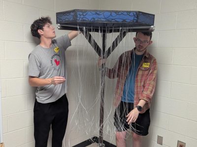
(from left to right)
Jacob Merritt (14a), Nick Romsdal (14b), Alexi Freemon (14a), Eric Tran (14b), Ezekiel Cortez (14a), Kylie Truong (14b), George Songers (14b)
Problem Statement
The fiber optic tree is designed as a freestanding but wall-supported sensory installation located in the corner of the classroom. The structure will be approximately six feet tall with a canopy radius of roughly three feet, fitting comfortably beneath the eight-foot ceiling height of the room. The frame will be constructed entirely from modular 80/20 aluminum extrusion to provide a rigid, lightweight structure capable of supporting the lighting and fiber optic components. Fiber optic strands will hang downward from the upper frame to create a curtain of glowing fibers that students can visually engage with. LED light sources controlled by a Raspberry Pi will illuminate the fiber bundles, allowing adjustable brightness and programmable color transitions. The electronics, including the LED driver and power supply, will be enclosed in a protective housing mounted near the top of the frame and concealed from direct view. To ensure safety, the frame will be anchored to the adjacent walls using structural brackets attached to the cinder block wall.
Design Specifications
The fiber optic tree must satisfy several design specifications to ensure safety, functionality, and compatibility with the classroom environment. The overall height of the structure must not exceed six feet to maintain clearance below the eight-foot classroom ceiling. The canopy of fiber optics should extend to a radius of approximately three feet to create sufficient visual coverage while remaining within the corner installation space. The structure must support between 35 and 45 fiber optic bundles, each approximately four inches in diameter. The lighting system will be controlled by a Raspberry Pi microcontroller to allow programmable color patterns and adjustable brightness. Electrical components must operate from a UL-certified power supply compatible with a standard 120 V wall outlet. The frame must be constructed from durable 80/20 aluminum extrusion and include soft protective coverings to prevent injury. Finally, the system must be anchored to the wall using structural brackets to prevent tipping when students interact with the installation.
Background Research
The fiber optic tree must satisfy several design specifications to ensure safety, functionality, and compatibility with the classroom environment. The overall height of the structure must not exceed six feet to maintain clearance below the eight-foot classroom ceiling. The canopy of fiber optics should extend to a radius of approximately three feet to create sufficient visual coverage while remaining within the corner installation space. The structure must support between 35 and 45 fiber optic bundles, each approximately four inches in diameter. The lighting system will be controlled by a Raspberry Pi microcontroller to allow programmable color patterns and adjustable brightness. Electrical components must operate from a UL-certified power supply compatible with a standard 120 V wall outlet. The frame must be constructed from durable 80/20 aluminum extrusion and include soft protective coverings to prevent injury. Finally, the system must be anchored to the wall using structural brackets to prevent tipping when students interact with the installation.
Concept Design 1
The first concept design is a modular frame made out of 80/20 that has the fiber optic cables hanging near the walls. This is similar to how “vine walls” are designed. There would be thicker boxed walls at the top of the frame to house the electronics.
Concept Design 2
The next concept is the a modular frame that comes out into the room. The shape of this would be a quarter-circle. The top would be open to allow light to illuminate at the top.
Concept Design 3
The last design is the same frame structure as design 2, but this time, there are more braces on the legs holding the quarter-circle up, and the top is covered. This allows for the electronics to be distributed more evenly along the base plate. This design allows for more support and electrical safety to protect the students.
Selected Concept Design
The selected design for the fiber optic tree uses a modular aluminum extrusion frame combined with programmable LED lighting and hanging fiber optic strands to create a visually immersive sensory element. The frame structure provides a rigid support system capable of holding the fiber optic bundles while maintaining a compact footprint within the classroom corner. LED illumination controlled through a Raspberry Pi allows the lighting patterns to be customized and adjusted for different sensory needs. By suspending the fiber optic strands from the upper frame, the design creates a curtain-like canopy that mimics the appearance of glowing vegetation while remaining lightweight and safe. Mounting the electronics near the top of the frame helps conceal the hardware while keeping it inaccessible to students. Anchoring the frame to the wall ensures the installation remains stable during interaction, reducing the risk of tipping.
Decision Matrix
Overview of Selected Design
Structural Design:
The fiber optic tree will be approximately 6 ft tall with a canopy radius of about 3 ft, allowing it to fit within the corner of the sensory room while remaining below the 8 ft classroom ceiling.
The structural frame is constructed using 80/20 aluminum extrusion, providing a rigid, lightweight, and modular support structure.
Lighting System:
The lighting system uses LED light sources connected to fiber optic cables to illuminate the hanging strands.
LED color patterns and brightness levels will be controlled using a Raspberry Pi microcontroller, allowing programmable color changes and adjustable light intensity.
Safety Features:
Soft protective coverings will be installed over exposed frame edges to reduce the risk of injury if students come into contact with the structure.
The design ensures that electrical components remain inaccessible to students, while the fiber optic strands remain safe to view and interact with.
Describe Design Details
Several critical design features were incorporated to ensure the fiber optic tree meets both functional and safety requirements. First, the structural frame is constructed using 80/20 aluminum extrusion, which provides high rigidity while allowing modular assembly using corner brackets and T-slot fasteners. Soft protective coverings are added to exposed frame edges to prevent injury if students make contact with the structure. Second, the fiber optic bundles are suspended from the top of the frame so that the illuminated strands hang downward in a curtain formation. This configuration allows the light sources to remain protected while providing an immersive visual effect throughout the canopy. Third, the lighting system is controlled using a Raspberry Pi microcontroller that manages LED color changes and brightness levels. This allows instructors to adjust the visual stimulation based on student needs. The electrical components are housed in a protective enclosure mounted on the frame, and the entire structure is secured to the classroom wall using structural brackets to ensure the tree remains stable under student interaction.
Engineering Analysis 1
Moment Analysis Description:
The moment analysis starts by finding the normal force of the entire fiber optic free by balancing the moments. If the normal force is located outside of the base, then it would be unstable. However, the normal force is inside the length of the supporting legs of the tree, making it stable.
Then, a hypothetical downward force at the edge of the radius of the quarter circle was found. This is the force that would cause the normal force to move outside the accepted range of stability for the tree. The outcome of this was that 2054 lbf directly downwards was needed to tip the stand over.
Lastly, a hypothetical horizontal force was applied at the top edge of the tree. Then the friction coefficient between the base of the tree and the floor was found. If the friction coefficient is higher than the calculated value, then the tree has a chance of tipping.
Moment analysis of the sensory board would justify the size and safety factor for wall mounts.
Engineering Analysis 2
To ensure the LEDs used in the tree do not burn out over time, resistors will be installed in each LED circuit. Using the maximum current allowed on GPIO pins of 16 mA, paired with 3.3 V logic, the maximum resistance necessary is 81.25 Ohms. As this number is difficult to find in production, the team will sacrifice light intensity for safety by rounding up to the next available value.
From here the light intensity can be further modified by installing a potentiometer into the circuit.
Engineering Analysis 3
The last engineering analysis done on this was to look at the tensile strength of the fiber optic cables.
The yield stress of the fiber optic cables is approximately 195.6 x 10^3 psi.
A hypothetical force of 500 pounds was applied to the cables to see the reaction. The diameter of the cables is approximately (1/16) of an inch. The working stress is approximately 162.97 x 10^s psi.
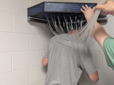
Since the working stress is lower than the yield stress, the cables will not fail from being pulled on. This means they can be used to be the main attraction for the room, allowing students to run their hands through the cables.
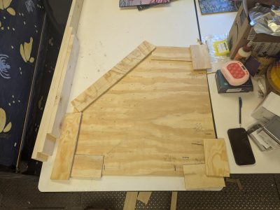
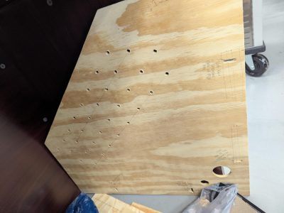
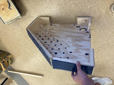
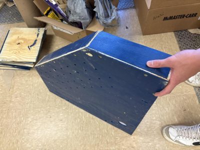
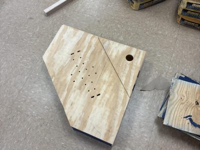
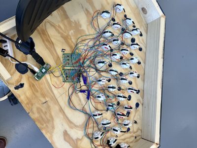
The actual process for building the fiber optic tree was relatively simple for the physical building but difficult for the electrical layouts. In order to build the electrical housing, we decided to build a frame out of leftover wood and cut sectioned plywood in order to have an outside finish that worked well. We attached these by using screws and nails depending on the specific use of the part. Then we assembled it with a hinge in order to easily access the electrical assembly inside. Furthermore, we painted and detailed the housing to match our theme. For the base frame, we used 80/20 aluminum extrusion. This worked easily and well. We designed supports at the top to hold the extra weight of the housing and electrical work. Then we were able to include anchor points to attach to the cinderblock wall to avoid tipping. As for the electrical assembly, it was difficult to find an optimal way to keep the fiberoptic cables from being pulled out. The solution for this was to 3D print small reels that would hold each strand of fiber optic cables. To ensure light made it through the entirety of the fibers, heat shrink tubing was used to hold the tip of the LEDs against one end of the fibers. This method proved moderately successful as a couple of LEDs had weakened tubing which allowed for some light to shine through. Soldering the electronics for the tree proved to be tedious with over 140 individual solder joints being needed. All LEDs were soldered to NPN transistors to manage the current load on the GPIO pins seleceted for controlling the LEDs, with power being supplied from the onboard 5V power pin.
Testing Results
The test for the tree structurally was if the housing would be able to be supported by the 80/20 frame. When we put the housing on, it was fastened securely, and was supported easily.
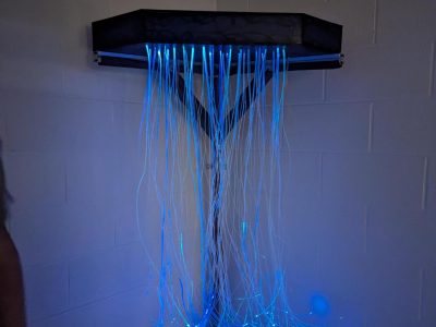
The results of testing the fiber optic cables was that it turned on!
Completed Design Photos
Instructions for Safe Use
Plug in the extension cord to the wall outlet
Plug the raspberry pi into the extension cord
Turn on the pi
Run your hands through the cables
Do not put these cables in your mouth
Do not yank on these cables
Do not attempt to climb, jump on, or pull on the tree in any fashion
Project Summary/Reflection
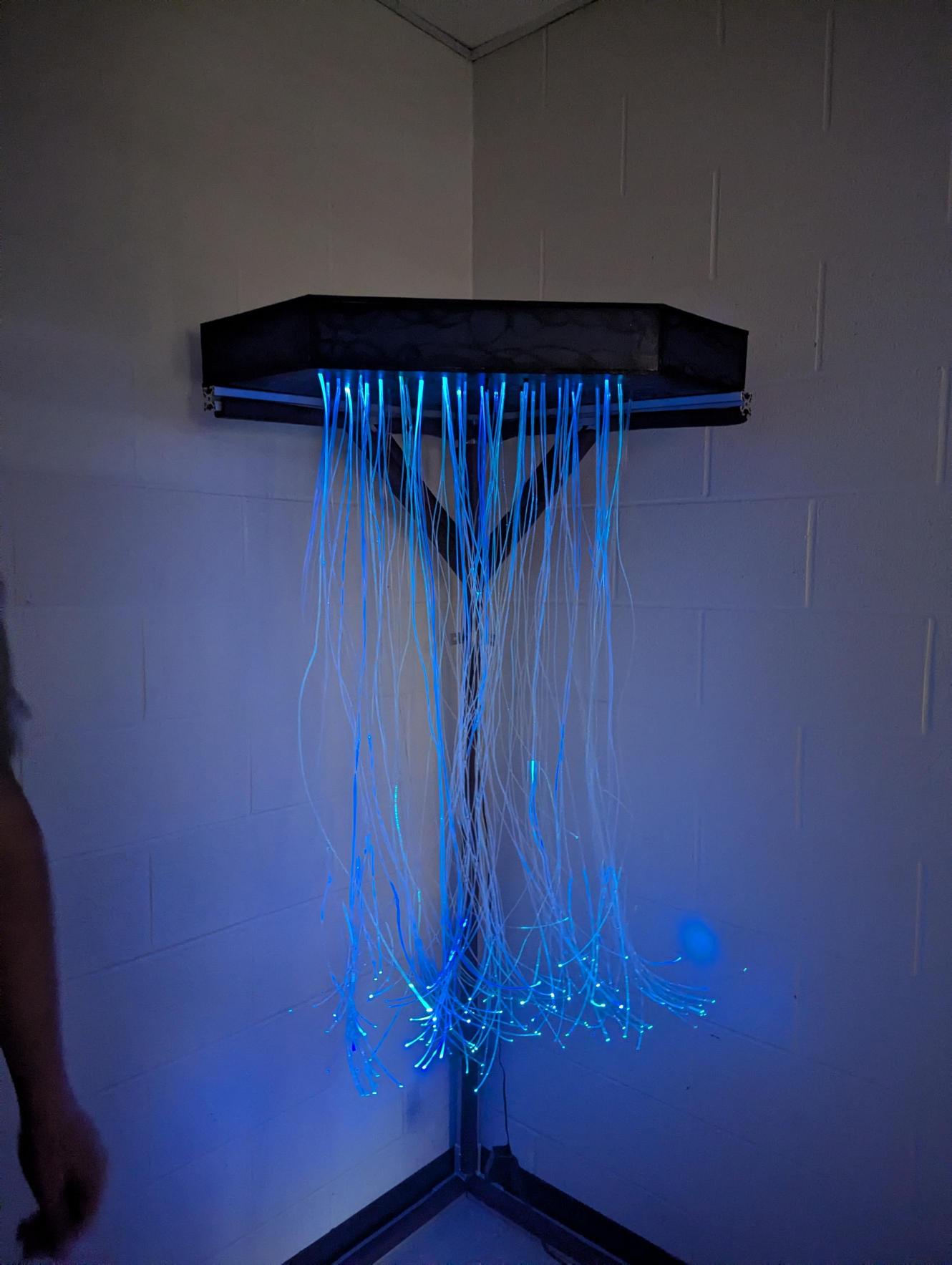
Overall, the tree was successfully mounted to the wall, having a beautiful blue shine through the cables. There is foam on the corners of the 80/20 frame, helping prevent harm to student if they end up hitting it. There frame inside the housing is actually broken into two pieces, allowing for the top of the housing the be removed from the frame. There is a door on top as well to help access the electronics without having to take off the whole top.
Looking back at the project now, we wish we would’ve spent more time looking over the specific electrical layout of the tree. The strands themselves are relatively bright, but not to the lengths we wish they would be. Choosing different fiber optic cables would have given us a side flow effect but would of have costed significantly more. So a lot of our time went toward trimming the specific cables and also sanding down the sides of such cables in order to give the light some resistance to reflect off of. This was a time costly effort, but in order to stay in budget, it had to be done. With hindsight, the electrical wiring could be improved to increase the longevity of the lights and improve manufacturability. Overall, as a team I think we are pleased with the result, but definitely were some areas where we could have saw vast improvement through our whole process.
Overall, this project was enjoyable to learn to work with two different teams (including coordination and timing of the deliverables), using creative solutions to solve unaccounted for problems, and connecting what is taught in class to how to apply it in a real-world scenario.