The family is in need of a motorized, adjustable activity chair for Avonlea. They are open to possible adaptation of the current chair that they have.
Gwen Behaylo, Sophie Hayes, Ashley Meadows, Sam Chumney
Problem Statement
Our child has limited strength and mobility, and needs an activity chair to move around. The family would like a motorized chair to allow her more independence. In addition, they would like for the seatback, headrest, armrest, and footrest to be adjustable, and its height to be electronically adjustable. Their current chair has small wheels that have a difficult time going over rougher terrain like a gravel driveway, so they will need more rugged wheels. Weight is also a concern as it will need to be moved in and out of their car.
Design Specifications
Motorized
Lightweight
Able to ride over rough terrain, like gravel driveway
Motorized adjustable height
Adjustable head support with side supports
Foldable arm rests
Lap restraint, possible chest restraint
Adjustable footrest
Designed to grow with the child
Background Research
Our background research involved us analyzing Avonlea’s current chair and searching for different methods to improve her new chair to her needs. We first used her current chair, the Rifton Activity chair, for reference on some overall design concepts. We also looked into past projects that were similar to ours. As for the motor, we looked into pre-programmed drive kits for wheelchairs to attach to the chair. We also researched several methods to adjust the seat, head, and armrests for the chair with methods such as: hydraulics or motorized screw.
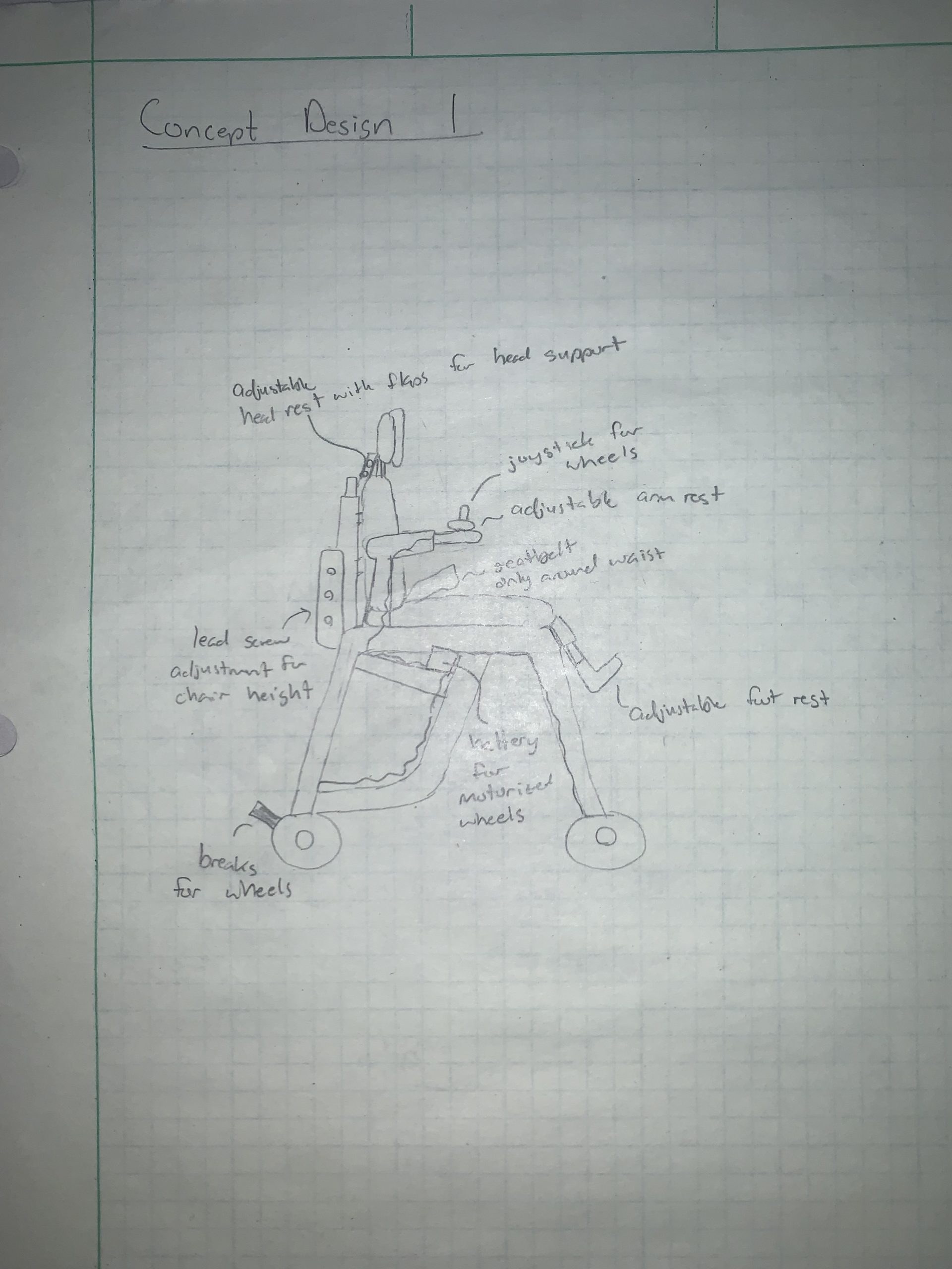
Concept Design 1
In this design, we tried to focus on making the chair adjustable so it can grow with her as needed. We used motorized wheels controlled by a joystick in one of the arm rests so she can move around independently with a box-like area under the seat to hold the battery and receiver. We made the headrest, the arm rests, the back of the seat, and the footrest adjustable to different heights. We also added a seatbelt to keep her secure.
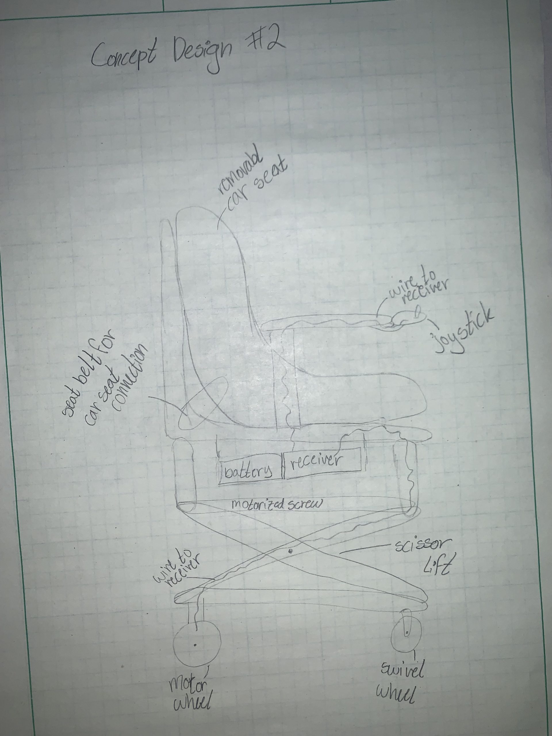
Concept Design 2
In this design, we decided to use a detachable car seat for the chair for easier collapsibility. We still have the motorized wheels, the joystick, and the place for the battery and receiver. We also added a scissor lift with a motorized screw so that the chair is easy to lift and lower to different heights. We also changed the front wheels to swivel wheels to make turning easier.
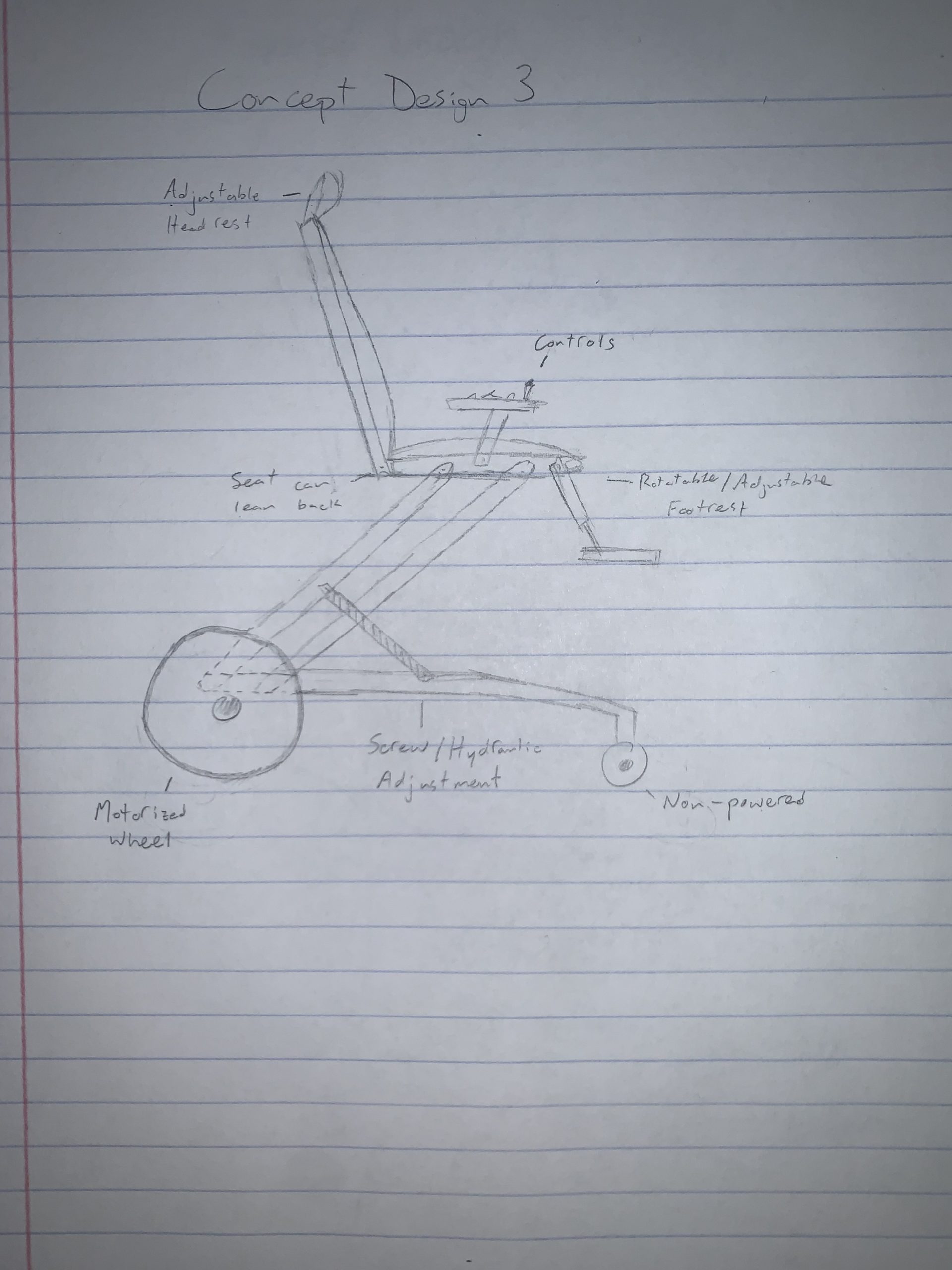
Concept Design 3
This design differs from the previous two in that the lift mechanism utilizes a parallel linkage design with screw type motorized linear actuator. The arrangement is similar to double wishbone suspension with the chair taking the place of the hub and the linear actuator taking the place of the shock. This design also includes a motorized rear wheel drive train with controls located on the armrest. The seat is adjustable to hold her comfortably and securely.
Decision Matrix
Overview of Selected Design
We selected concept design 2 to feature the scissor lift design for the height adjustment; however, we are taking elements from design 1 and 3 to incorporate into the design. We are replacing the car seat with a modified chair and taking all the adjustable parts from designs 1 and 3 so that Avonlea can grow with the chair.
Describe Design Details
Our design involves using a past chair that Avonlea had and modifying it by motorizing the wheels and the height adjustments. We are replacing the hydraulic cylinder with a linear actuator to make lowering and raising the height much easier for the family. We are also buying a driver kit to motorize the whole chair that will be controlled by a joystick. Since Avonlea has grown, we will be replacing her old chair parts with new cushions that are adjusted to her size now and add a headrest since her old chair had no support for her head. With the motor modifications, we need to replace the front and back wheels and their mounts with parts we design and will manufacture using. We also will manufacture new mounts for the linear actuator as well as the mount for the battery and all of the electronics.
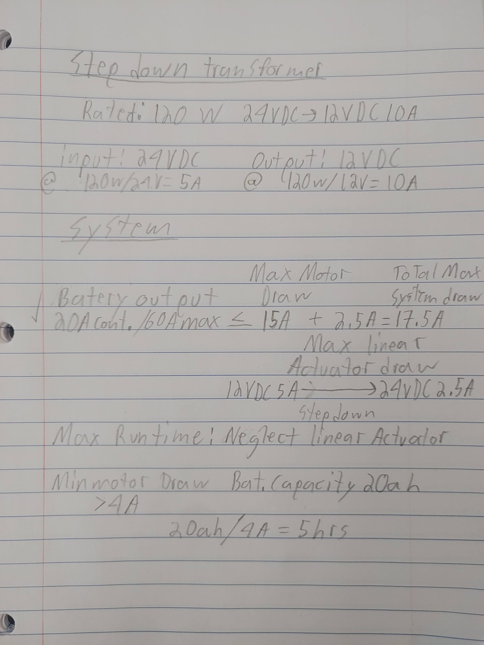
Engineering Analysis 1
For engineering analysis 1, we have calculated the maximum current draw of the system to 17.5 Amps. This is less than the manufacturer rated 20Amp continuous/60Amp max current output of our battery. This means that the battery should never see more current draw than it is rated to handle. The manufacturer rates the motor kit as being able to travel up to 25km with our selected battery, and, at <4Amps minimum current draw (at 4mph), that should result in up to approximately 5 hours of continuous run time. Assuming regular day to day operation patterns, this should be more than adequate in allowing the child to operate the chair all day on a single charge. In addition, each motor can produce up to 12 N-m of torque, plenty for a chair only rated to a load capacity of 70 lbs.
Engineering Analysis 2
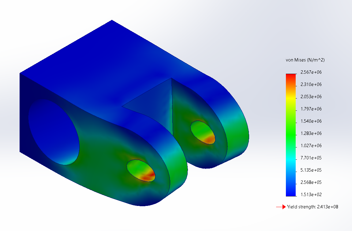
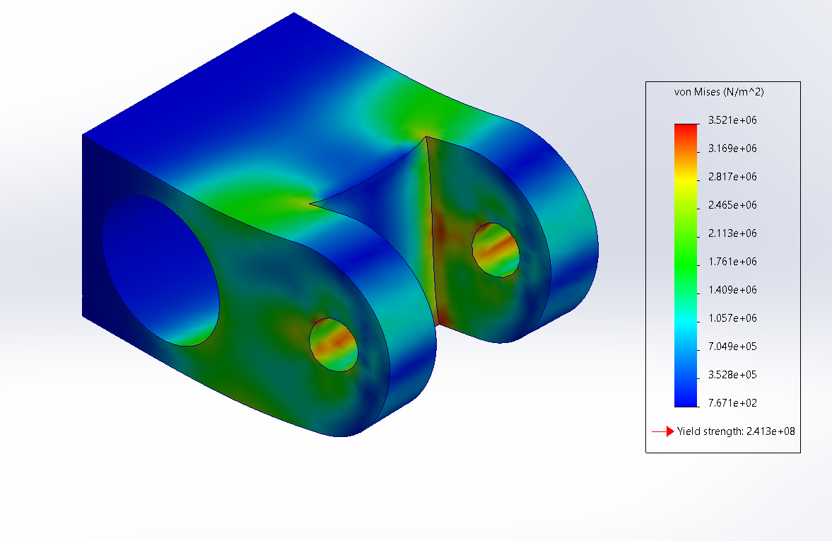
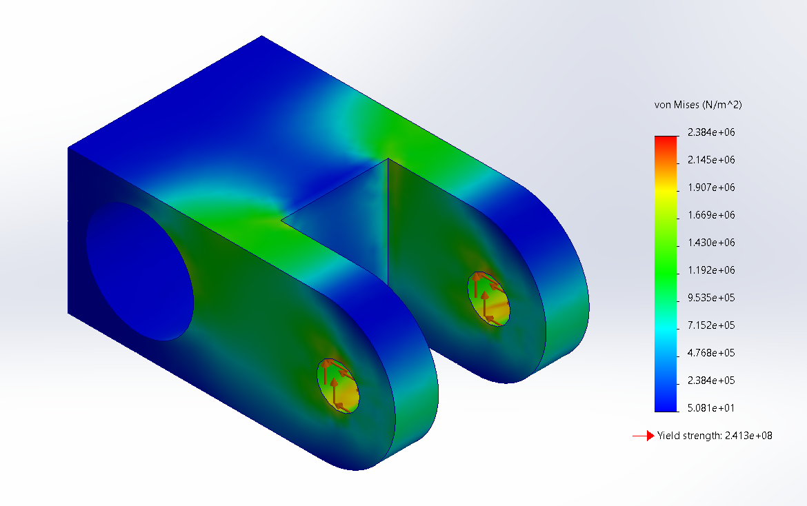
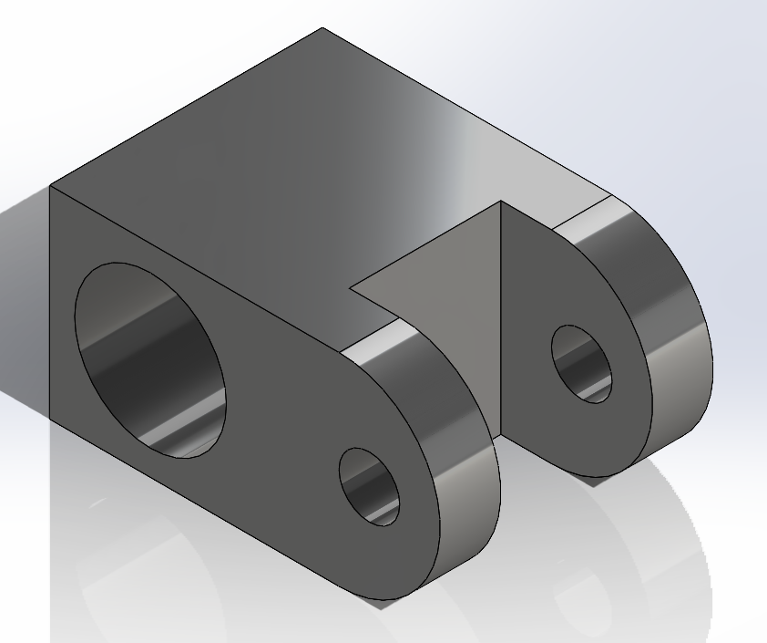
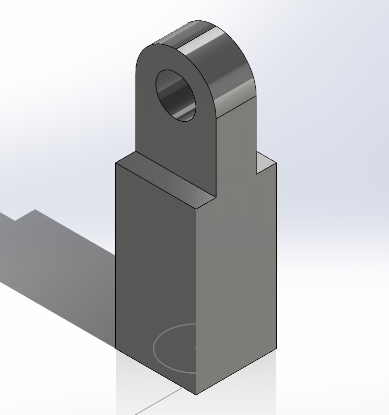
For engineering analysis 2, we calculated stress on the linear actuator mounts under load in both the fully-lowered and fully-raised positions. Deflections shown are exaggerated for visualization.
Engineering Analysis 3
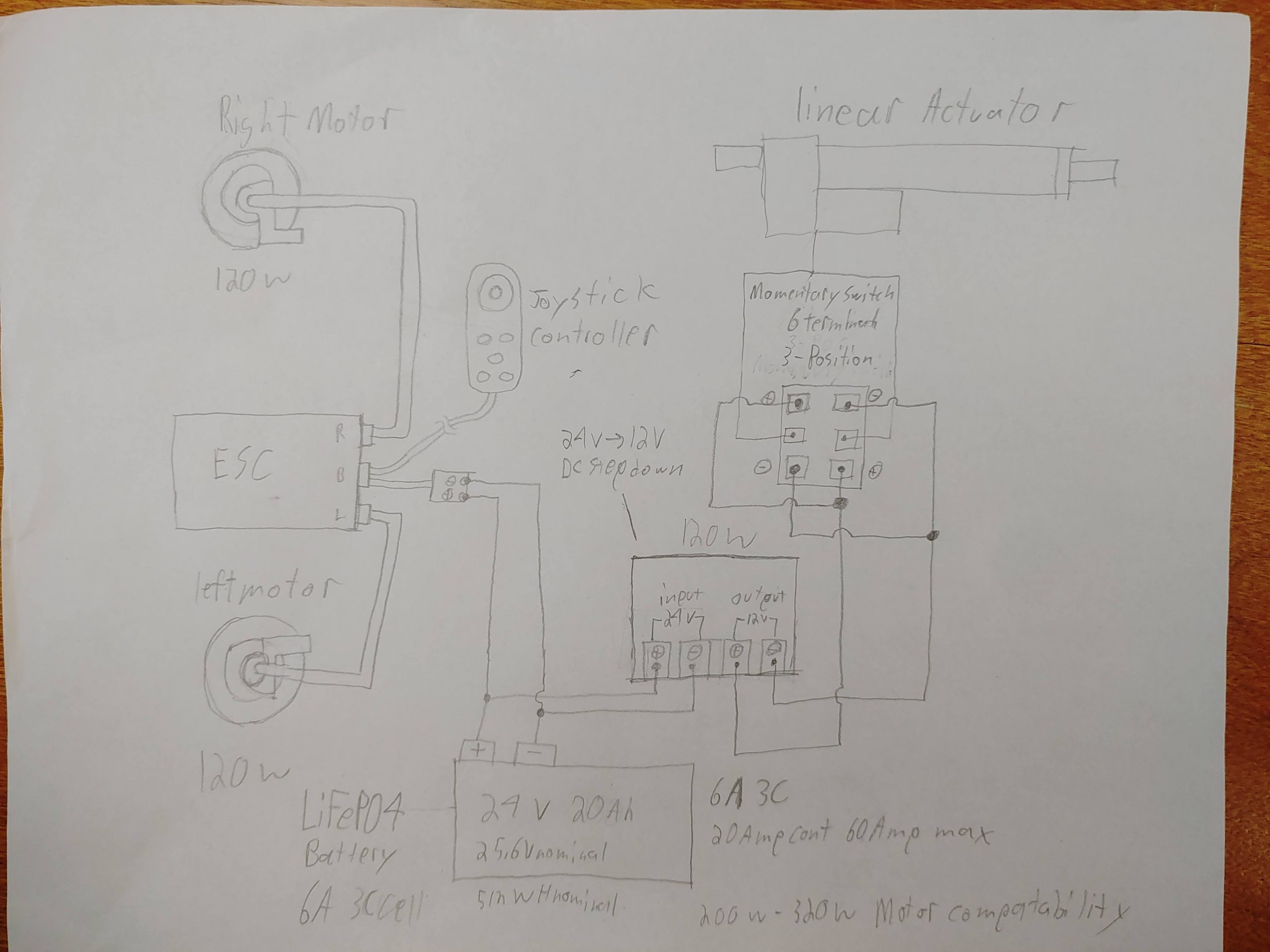
For engineering analysis 3, we developed a wiring diagram for all powered components of the chair. The motors, ESC, and joystick all come as a kit with plugs for battery connection and charging included. The kit is rated for 24v DC. The linear actuator is rated for 12v DC with a max current draw of 5 Amps. The motor ESC will be connected to the battery in parallel with the linear actuator circuit. Between the linear actuator switch and the battery, a 24v DC to 12v DC 10Amp step down transformer will be wired in series in order to provide the linear actuator with the required 12v DC.
The manufacturing process mainly consisted of replacing plastic parts from the old frame with new aluminum parts or adding on mounts for new parts we designed. These manufacturing steps included using the band saw, belt sander/disc grinder, mill, water jet, and the drill press. For the rest, we used the 3-D printers to make smaller pieces that would support the lighter parts, and we replaced the seat with new foam and covers.
Disassemble old chair and take out pieces that would not be used to replace with new/modified pieces
Choose aluminum material that had the thickness required for the parts
Cut out material with band saw and square up with the mill
Water jet pieces that had very small technical parts or curves on them that other machinery could not manufacture
Use belt sander/disc grinder to even out surfaces or round out sharp corners
Cut out/resize holes using the drill press
Assemble the whole chair and wire all electrical components


