The goal of this project is to design and assemble a walker for a child having issues with mobility and supporting themself. The walker will grant the child a chance to walk easier as well as build core strength and promote abdominal muscle growth.
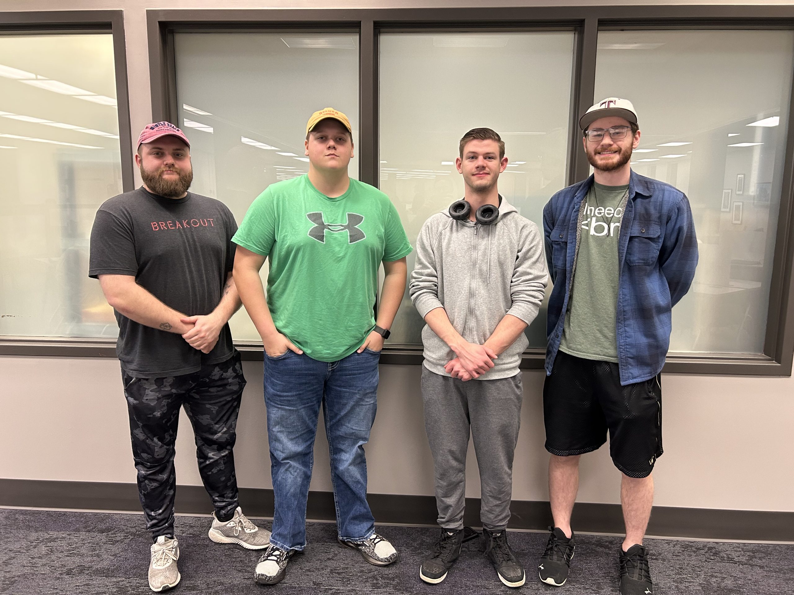
Alex Barker, Hunter Justice, Cole LeSar, Jordan Frerichs
Problem Statement
The child we have been assigned has a condition that prevents her from being able to support herself upright or walk in a proper manner. Our team has been tasked to design or improve upon a walker that will better suit the specific needs of the child. Upon meeting the family, they addressed her dislike of her current walker and some of the faults that cause issues with her day-to-day use.
A major issue the family faces is their current walker relies on a type of abdomen securing apparatus which makes the child uncomfortable and essentially holds her up. The family wishes for a design that does not have a means for securing the child in and promotes muscle growth and posture improvement. We have also been tasked with providing a way for the walker to be possibly motorized and implement better-designed armrests so as she practices walking she can take breaks when she becomes tired.
Design Specifications
lightweight
Motorized
Armrests
Compact
Locking- wheels
Adjustable armrests
No abdominal support apparatus
Background Research
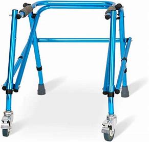
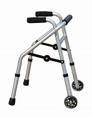
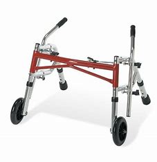
As we tried to work on some ideas for the walker, we reflected on several youth-sized walkers currently being produced. Meeting with the family of the child provided us with insight into the current walker they are using as well as why they dislike it.
From the research we conducted, we were able to come up with some conceptual ideas that would best fit the needs of the child.
Concept Design 1
The first concept we created revolves around the idea of designing a walker with forward-moving caster-style wheels in the front and swivel casters on the back. This design would allow for a more controlled turn of the walker. The family mentioned their discontent with how all of their current walker’s wheels are able to swivel 360°. This results in a harder turn for the child as she walks through obstacles such as hallways and door frames.
The family also made sure to express the issue of the weight of the walker. This walker design would utilize an aluminum frame to allow more ease for a small child to move the walker on their own without the help of a parent.
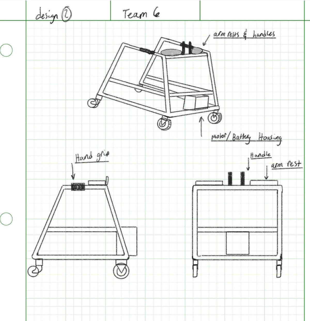
Concept Design 2
Our second design involves the possibility of making a walker which could be motorized. The goal of the motor being implemented is not to let the child become reliant on it, but to use it as a backup for difficult terrain or help when they become tired from walking.
The motor will be controlled by the front handles located next to the armrests. This walker utilizes a front-wheel drive concept with motorized caster-style wheels in the front and swivel castor wheels on the back. The handles for operating the motorized wheels will be located next to the armrests for ease of access.
This walker revolves around a more traditional style of walker more commonly seen.
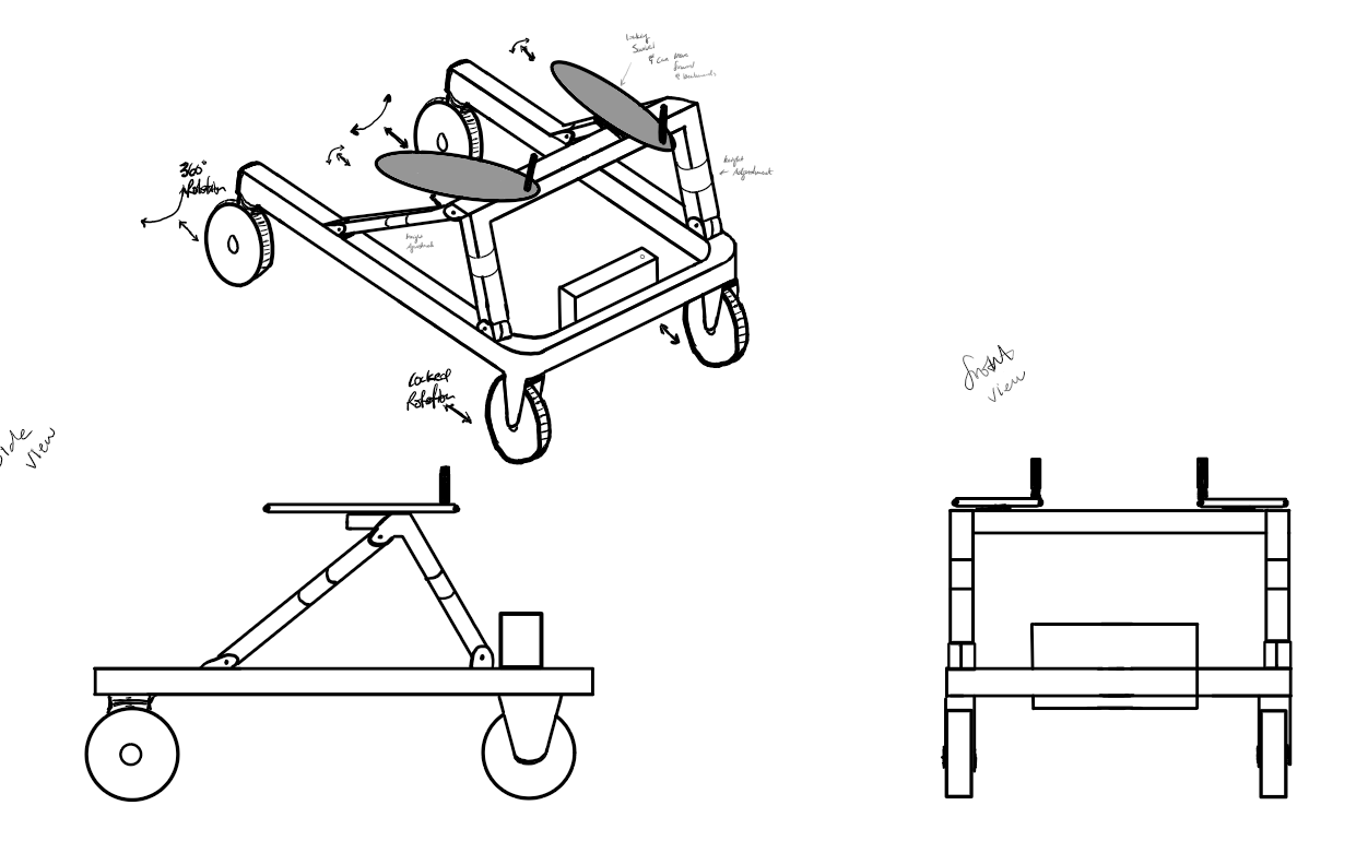
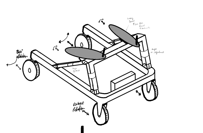
Concept Design 3
The third design focuses on portability, mobility, and adjustability. Similar to design 2 it integrates the locked motorized front wheels and also free-rotating back wheels. The battery and motor box can be removed if necessary. The forearm rests are designed to move forward and backward and rotate in and out. This allows adjustability as she grow. The links are also adjustable to account for change in her height over time. Aluminum will be the main material because it will help reduce overall weight.
It is designed to be able to be taken apart with relative ease. The battery box, forearm rests, and support links can be removed by lifting the supports out (adjustable support can be unlocked and lifted up). Making the chassis fold down would also be something worth incorporating.
Selected Concept Design
After considering the concepts above, we decided to select Concept 3 because of the higher score it received on the decision matrix.
Decision Matrix
Overview of Selected Design
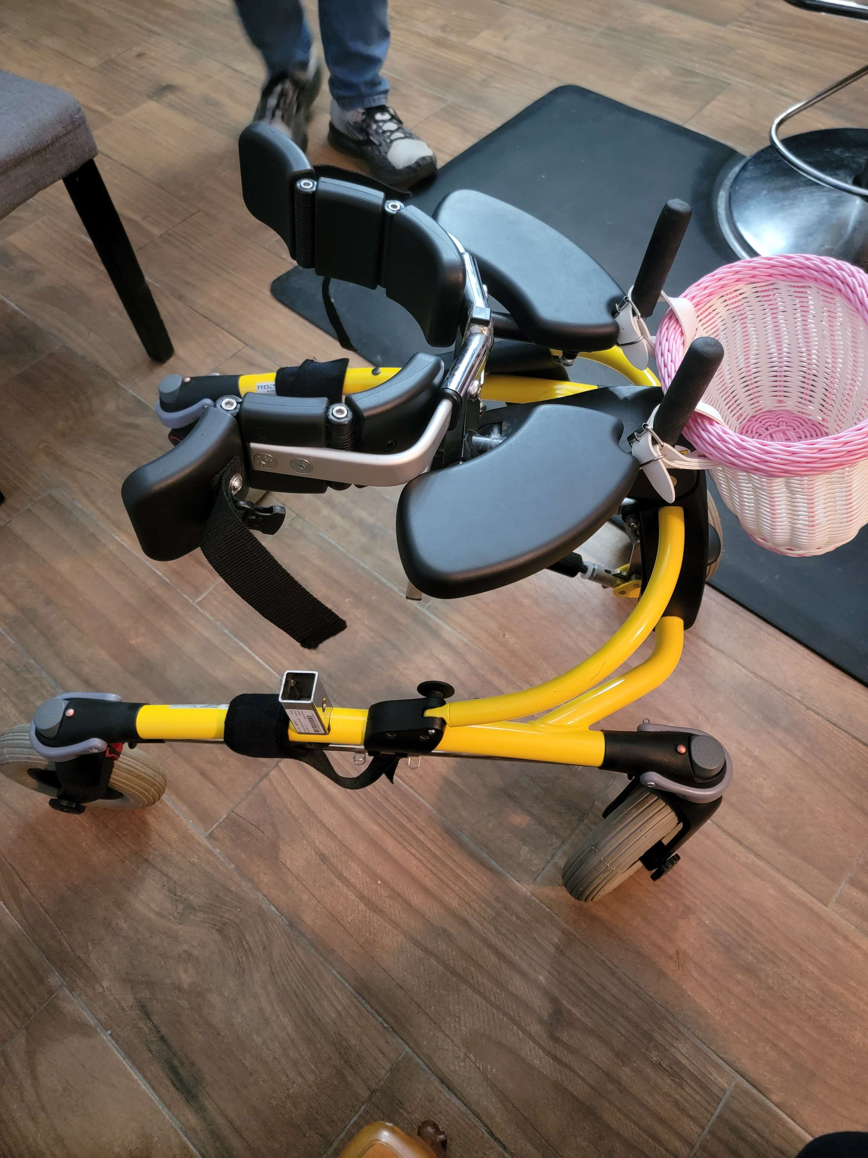
After considering and evaluating the specific requests of the family, we as a group decided to build upon a walker that was found through research completed after the preliminary design stage.
The Drive Medical KA1200-2GWp Nimbo Posterior Walker is the walker we selected. This specific type of walker comes in sizes ranging from extra small to large. After receiving the child’s size parameters from the parents, we found that a small-size walker of this type would be the best fit for her. The walker possesses the following traits:
Aluminum alloy frame
Lightweight (12.8 lbs)
Collapsable frame for transportation
Adjustable height
Modifiable
Higher maximum weight capacity (85lbs)
Under further review, it was a collective decision to cancel the idea of the motorized possibility for the walker. After consulting with the family of Avonlea, they agreed that the main priority of the walker is to be a learning tool for her to gain the ability to walk. We felt the motor would provide a chance for her to become too dependent on the motorized option. The weight of the motor and power source would also inhibit the chances of her being able to push the walker more easily.
Describe Design Details
The following modifications will be made to the walker:
Attaching adjustable forearm rests for the comfort of the child
Implementing handles on the frame to increase the ease of turning the walker around obstacles
Applying a cross-bar support across the handles of the frame for the armrests
Engineering Analysis 1
Due to the drastic change in the weight of this walker compared to Avonlea’s current walker, we decided to compute the force required to accelerate the walker. For this we assumed the following:
Avg. walking speed = 1-1.25 mph
Friction force of an applicable surface she would encounter
Maximum walker weight (after added modifications) = 20lbs
This yielded that She would need to exert a force of approximately 2.52-2.88 lbf for her to move the walker.
Engineering Analysis 2
Stress analysis was conducted on a hypothetical, 30″ long aluminum hollow rod to test the limits of our stress application. The following assumptions were made:
Outer diameter = 1″
Inner diameter = 7/8″
Thickness = 1/16″
Yield strength = 30 ksi
The goal was to see how much stress could be applied where we can still maintain a factor of safety of at least 3. This force, which was transverse and located in the middle of the beam, wound up being 27.08 lbf.
Engineering Analysis 3
A CAD model was drawn up to represent the stress application on the walker after the proposed modifications were made. This includes a riser and armrests. The applied force was 50lbf on each pad (far exceeding her current weight). This allowed us to be confident in the fact that the walker could withstand all of her weight and then some throughout her childhood. The maximum deflection was 0.006″, and indicated a critical location on the armrests: this told the team that the exact placement of the armrests would need to be heavily considered. The armrests having excess overhang (with respect to the risers) caused unnecessary stress in the ends of the armrests, which should certainly be avoided.
The Fabrication Process of this walker has consisted of improving the design for more applicable use for the child we have been assigned. We made no Major alterations to the walker itself besides preparing holes into the frame for armrest attachment. The following was conducted :
Cutting and sizing aluminum pipe for the armrest supports via saw and the milling machine
Sanding down and preparing the pieces of the armrest supports before welding
Using the milling machine for precise holes placed on the armrest supports
Removing factory hand grips from the walker
Applying the 3D-printed mounts for the armrest attachment to the aluminum supports
Removing Armrest supports for painting and fabrication
Cutting specific armrest bases out of MDF board, then applying proper padding and material for user safety
Testing Results
After assembling the walker, we ensured the bolts were fastened securely with enough torque so that the armrests would remain stable during operation. We opted to utilize nylon lock nuts since they would provide security as well as a means of preventing the bolts from backing out and becoming loose over time.
We inspected the walker by going through and ensuring that there would be no safety hazards such as sharp edges or exposed bolt threads.
As our final test, We ended up applying force to the armrests to ensure the walker could support a substantial amount of weight. We found the walker performed very well under the load of an average adult using the walker. This proves that the walker is suitable for a small child.
Completed Design Photos
Instructions for Safe Use
As with anything, it can be noticed that the walker should not be used with the chance of exceeding the weight limit (100lb or more).
With a folding frame, be cautious of pinch points and moving parts on the walker to prevent injury when folding for storage.
Ensuring the back wheel locks are in proper positions before use.
Project Summary/Reflection
We were able to finish the walker with no issues and deliver it to the family of the child. The walker performed very well as expected. The family was very pleased with the attributes of it being lightweight, transportable, and overall safe for use. The child was also very pleased and energetic when using the walker for the first time. This will be a great tool to aid in their development of walking skills as well as core strength building.
Overall, We found the walker to be a wonderful project to have the opportunity to work on. During the process, we developed a more keen sense of thought when it comes to the overall design as well as the process it takes in the development of products. We also developed a more keen idea of the ways to test the safety of the walker by utilizing the tools and knowledge we have gained from previous and prior classes.
We would like to extend our gratitude to Dr. Canfield, Jeff Randolph, Chris Mills, and the Mechanical Engineering Department for the help and guidance along the process of fabricating the walker.


