The goal of this project is to design and build an supportive chair/seat that can help a child suffering from cerebral palsy. This supportive chair will be designed to keep the child sitting comfortably in an upright position to improve their posture as they are able to play with their toys. This chair will be equipped with an adjustable lift to give the child full range of motion with their feet and a harness to keep the child comfortable strapped up to avoid possible sliding. The chair must be stationary. The parents/guardians expressed an interest of having a rocking feature on the chair to keep the child relax while playing with their toys. This chair must be able to accommodate the child’s growth through their preoperational years (ages two – seven years old).
(Left to right) Ty Goodwin, John Herberman, Josh Griffith, Anthony Onaghinor
Problem Statement
Noah is very limited in his range of mobility and is unable to sit up or walk. Due to this, he does not have the ability to easily enjoy his toys or interact with his peers.
Design Specifications
The supportive chair should be able to:
Remain stationary
Have adjustable height
Include limited range of rotation (360, 270, and/or 180 degree of rotation)
A potential rocking feature
Support seating in the upright position
Restrain movement of the torso and lower body
Provide full range of motion with legs
A table or other surface for toys
Background Research
We researched different methods of supporting our seat to make the most accommodating design possible. We considered several options on how to raise and lower the chair including using a scissor lift, a telescoping mechanism, or reuse a lift from an office-style chair. We also researched different options on the seat portion of the design and concluded that adding special supports to a preexisting chair is likely the most optimal approach.
Concept Design 1
Design concept one features a supportive chair with a telescoping lift that is attached to the back of the chair. This allows the user to be seated closer to the ground. However, having the lift connected to the back of the chair moves the center of rotation further away from the table. We could accommodate this by moving the axis of rotation to the center of the chair base. This would allow the chair and the table to pivot together around the same axis. This concept also includes a half circle chair that can be attached at the base.
Concept Design 2
Concept design 2 uses a simple scissor-lift mechanism to give the supportive chair adjustable height settings. The scissor-lift could be secured to a mounting-plate, which would serve as a base for the chair. Between the mounting plate and the chair, we could insert a ball joint, which would allow the chair to swivel in place. To accommodate a table, there could be sliders mounted on the sides of the chair. A simple, plastic table which spreads 180 degrees around the front of the chair could be made, with tabs that insert into the sliders on the side of the chair. Support legs would be required near the front of the table to keep it from bending under pressure. The chair itself can have safety straps to allow the child to sit upright without sliding out.
Concept Design 3
The third concept design would be to have a swivel base for the chair to provide 360 degrees rotation while being stationary to the ground. An adjustable lift would be added to the swivel have vertical range of motion. The chair will then be attached to the lift and will include an armrest, seat cushion for comfortability, a backrest (90 degrees to the seat of the chair) for lumbar and spine support, and a safety harness capable of supporting the child’s weight to avoid sliding out the chair. The main difference in this concept design is the attachment of a 3-piece round table surrounding the chair. The two pieces of the round table will each be attached to the backend of the chair and come around to the front of the chair. The third piece will be detachable to either end of the two round table pieces and folds into the other side of the two pieces. Both sides of the round table will be able to fold down to the arm rest to maintain compactness of the entire chair model.
Selected Concept Design
Upon comparing the 3 different concept designs to our design matrix, we selected concept design 2 as the best option to meet our standards for safety, usability, manufacturing, cost and accomplishingNoah’s needs for a supportive chair.
Decision Matrix
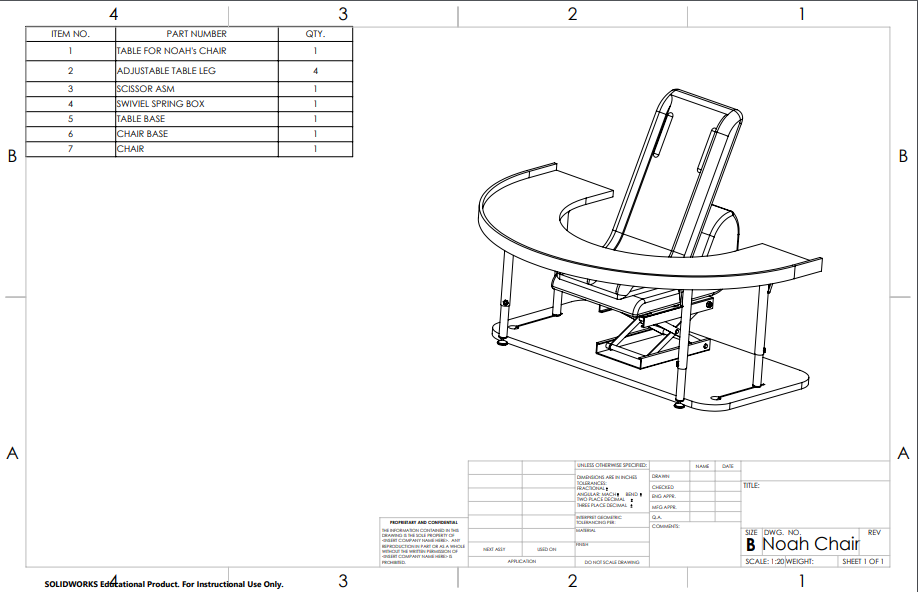
Overview of Selected Design
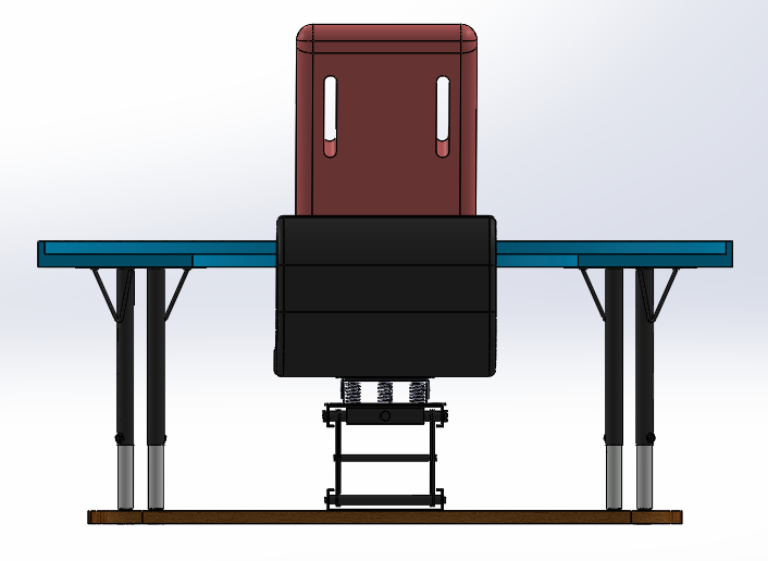
Our selected design will use a simple scissor-lift mechanism to give the supportive chair adjustable height settings. The scissor-lift will be secured to a mounting plate, which will serve as a base for the chair. Between the mounting plate and the chair, we will insert a rocking and swiveling metal plate, which will allow the chair to swivel in place. To accommodate a table, there will be slots cut into the base of the chair. A simple, plastic or MDF table which spreads 180 degrees around the front of the chair could be made, with legs that slide into the slots on the base of the chair.
Describe Design Details
This chair is designed for a 3-year-old with cerebral palsy.
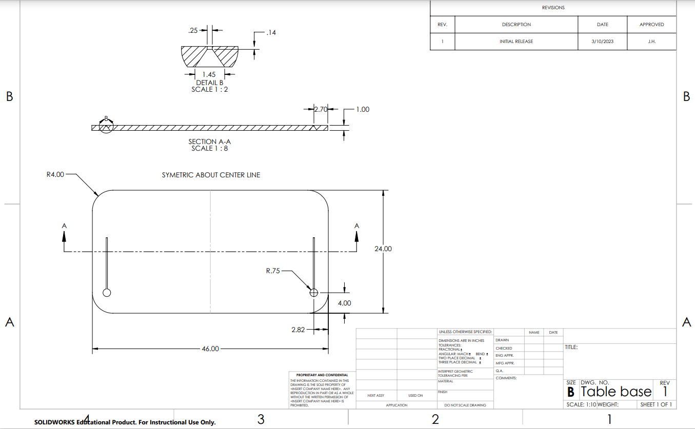
As a base, we plan to use a 46”x24”x1” slab of wood. This will serve as the mount for a scissor lift mechanism, approximately 14”x12” which has a height range of 3” to 15”. We are planning to repurpose a motorcycle lift for the scissor lift. It is adjusted by a screw on the top plate. We plan to mount a spring and plate part that allows for swiveling and rocking on top of the scissor lift and will add about 3” of height. Atop the swivel plate we’ll mount the chair itself, which is 5” from its base to the seat of the chair. That makes an overall height range of 12” to 24”. The chair is going to have straps that hold the child in place with a lipped front that will keep him from sliding forward out of the seat. The chair will be detachable from the rest of the device so that it can be placed on the floor where Noah likes to play.
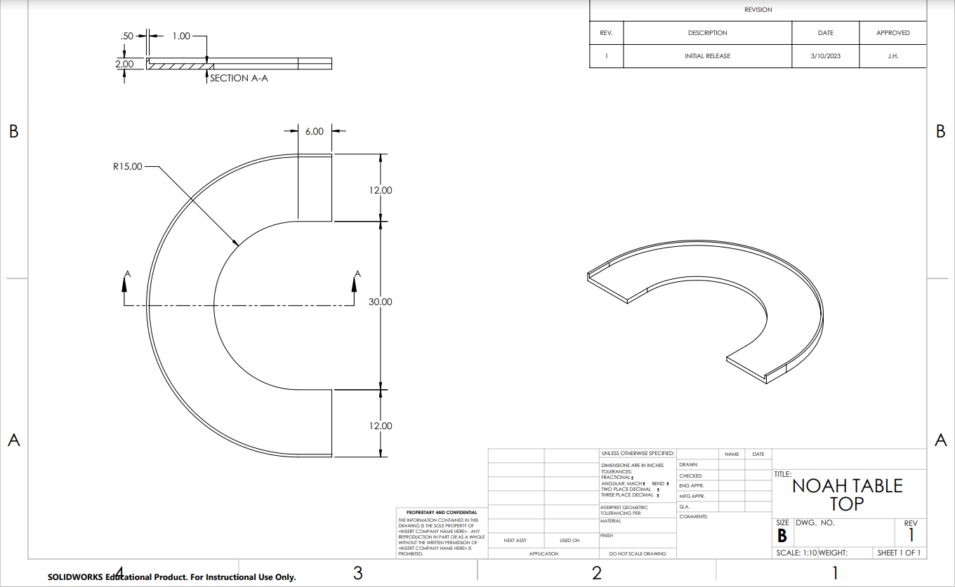
We plan to incorporate a table with adjustable legs that range from 21” to 30”. The table will be u-shaped, with an outer radius of 24” and an inner radius of 12”, and will span around the chair 180 degrees, with 6” linear sections added on at the ends. There will be a 1” back lip on the top of the table to keep toys and such from falling off. The legs will be attached to the table, foldable, and also able to be attached to the base, which will have slider sockets where the feet of the legs can slide in and be secured.
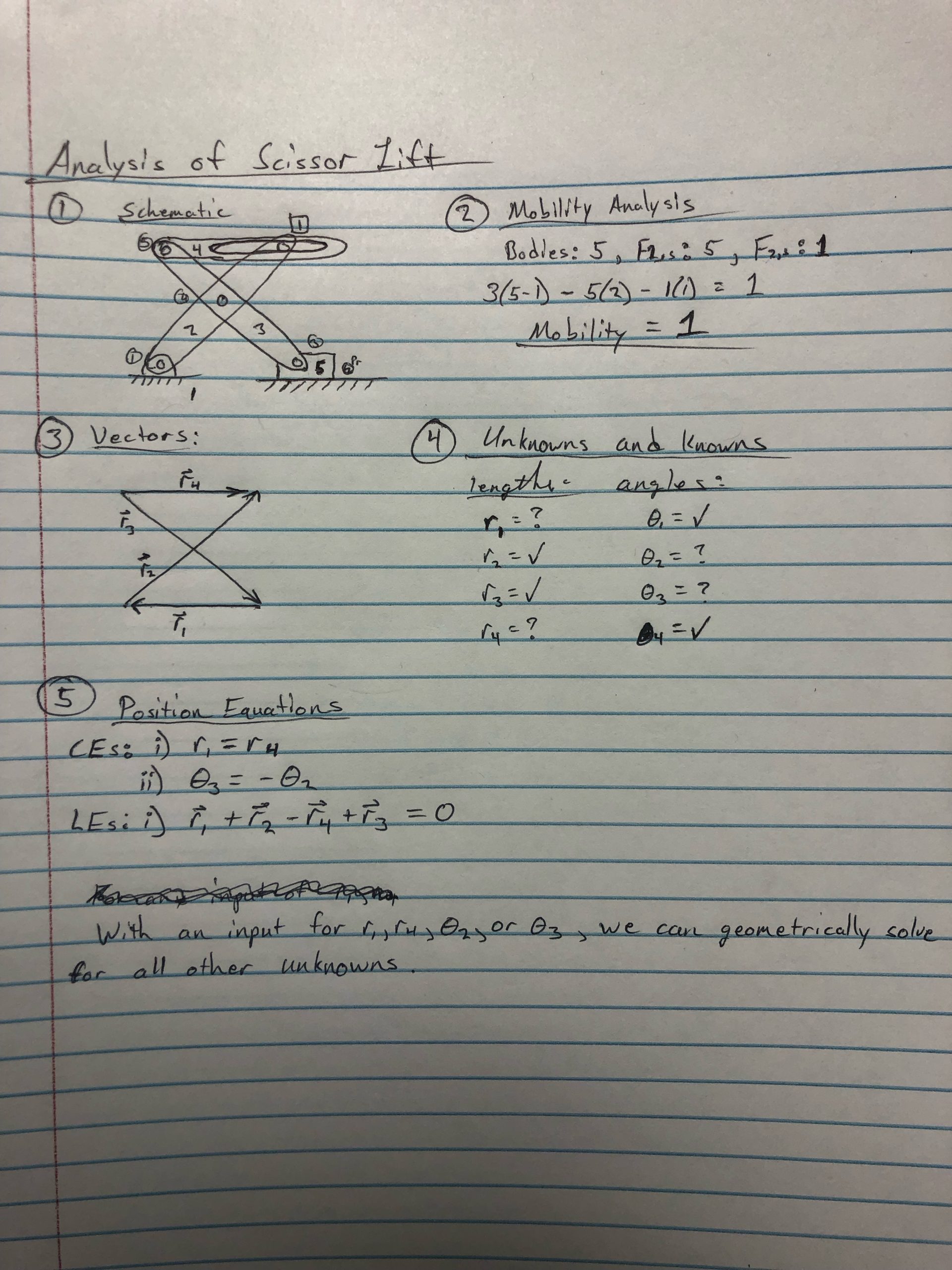
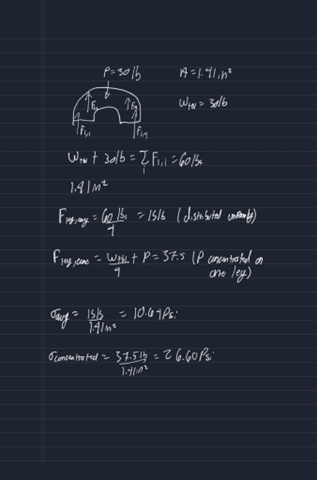
Engineering Analysis 1
We did a mechanical analysis on the scissor lift, including a schematic, a mobility analysis, a vector model, a list of knowns and unknowns, and a list of equations to solve for the unknowns.
Table: We used a water jet to cut out the design of our table. The table has been sanded down to remove any rough edges and attached 4 adjustable legs to the bottom of the table. Added a 1 in wooden lip to the back of the table to avoid slippage of toys. Painted the table completely white.
Scissor Lift and Swivel Rocker: Welded the swivel rocker to the top plate of the scissor lift and sway bars to the bottom side plate of the scissor lift. Exchange the previous springs on the rocker with lighter springs to support the child and the chair’s weight within the rocking motion. Welded the new springs to the rocker for additional support. Painted the scissor lift and swivel rocker matte black.
Floor Wedge and Chair: Constructed a wooden plate to go under the foam base wedge. Painted the wooden plate black. Bolted down the wooden plate to the rocker. Used adhesive spray on the base of the wedge in order to stick on 4 rows of velcro strips on the wedge. Attached 4 rows of Velcro strips to the wooden plate. Attached the base of the wedge to the wooden plate via velcro. Attached chair to foam wedge via velcro.
Previous
Next
Completed Design Photos
Previous
Next
Instructions for Safe Use
Chair needs to be strapped to the base with the black straps, in case the velcro comes detached. Weight limit of ~100 pounds not to be exceeded.
Project Summary/Reflection
We thank Jeff Randolph, Chris Mills, Dr. Stephen Canfield, and the Department of Mechanical Engineering for their support on this project and the entire EIME program.


