On our first meeting with Miss Melissa Draper, we learned that the rowing bike that was built during a previous semester had an issue and was no longer functioning. We took upon ourselves the tasks of fixing the previously built rowing bike and building a second one of our own. As our full team consists of two combined groups (9 people), we decided to split into three groups. One group was to focus on designing the drivetrain, one group focused on the frame, and the last group took on the steering and braking systems.
We were given the task of taking an existing design of a rowing bike, fixing it, and improving on the design for a new bike. The bike is designed for the special needs department at a local high school, specifically for those kids who are disabled and lack the control over their lower body. When talking to the special needs counselor at the school, she mentioned the bike needed to be able to fit multiple body types and weights, along with having a low input of effort to move the bike.
The previously built bike is having a drivetrain issue, but resetting the chains and adding a couple tensioners will be enough to get it working properly again.
For the new rowing bike design:
We have the bike which was built by teams across previous semesters, and will be taking many design cues from it. The frame and steering system will be very similar, but the drivetrain, braking, and body panels will be greatly improved.
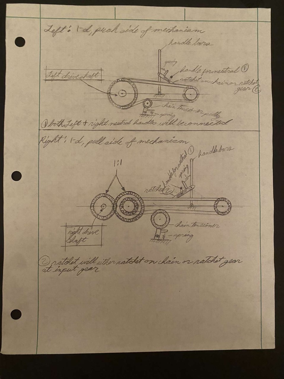
The first design for the driveline uses two separate chain drives and disengaging/reversible ratchets. Using the disengaging/reversible ratchets allows for the teacher to easily pull the rider and bike away from an obstacle the the bike may run into. The challenge with this design is finding a way to make the entire mechanism silent with little to no vibrations.
The frame design is very similar to the original with some structural improvements.

For braking, we have decided to order a standard bike brake kit and fit it to the rear wheels. This will be easier and faster than fabricating our own braking system.
For the steering, we have decided to keep with the original bike in using an electronic linear actuator to move a tie rod and change the angle of the wheels (shown in the first drawing). The only key difference in the design is the the bracket connecting the tie rod to the steering knuckle will be slightly shorter than the current bike, so that the angle of the wheels changes faster for the same actuator speed. The challenge of this system comes from the teacher sometimes needing to operate the steering for the student who is on the bike. Currently, the only steering control is a switch mounted on the handlebars, which is difficult to hold onto and operate while the student is rowing back and forth.
The first concept we have is for the control switch on the handlebars to have a plug, which can be removed and plugged into a separate remote with a longer cable. With this design, there is no chance of the rider accidentally inputting commands by hitting the handlebar switch while rowing, and the teacher can walk comfortably alongside the bike. The issue with this comes from balancing the length of the remote’s cable: too long and it could become tangled in the bike or around the riders arms, but too short and the teacher still won’t be in a comfortable position while the rider is rowing.
The second concept is to have a wireless remote which can operate the linear actuator while still having a handlebar switch as well. With this design the teacher would be able to keep a comfortable distance away from the bike while walking alongside it, operate the steering whenever needed, and there is no chance of injury for the teacher or rider becoming entangled. This design would need a safety built into it, though, so that the rider cannot accidentally enter a steering command while the teacher is trying to guide them.


For the drivetrain, we decided to go with the second concept which employs the use of one-way roller bearings. This concept will eliminate most noise and vibrations caused by a chain drive.
For the frame, we will keep similar dimensions to the current rowing bike. The biggest change will be widening the center so that the drivetrain concept will fit entirely inside.
For the steering system, we have decided to go with an entirely wireless remote system so as to eliminate the chance of wires becoming entangled with any moving parts on the bike. The battery that will drive this system will be mounted to the frame in an easily accessible place.
The final design we decided to choose was a combination
The drivetrain will make use of one-way roller bearings and a belt-driven axel to eliminate most of the noise that the current bike has. This will also make rowing much more smooth and allow for less friction, and thus easier coasting, than the current bike. The new drivetrain will also allow for bi-directional rowing, so that the bike is always propelled forward whether the rider is pushing or pulling the handlebars. Another major detail will be a lever attached to the belt tensioner, so that the tension can be easily removed from the belt and allow the axel to free spin. This will allow for the bike to be easily pulled backwards in the case that the rider becomes stuck.
The frame was designed using a finite element analysis technique. This means that we were able to use SolidWorks to run stress simulations on the frame design and add supports to any critical points discovered. We were also able to use SolidWorks to accurately measure the amount of material we would need to order.
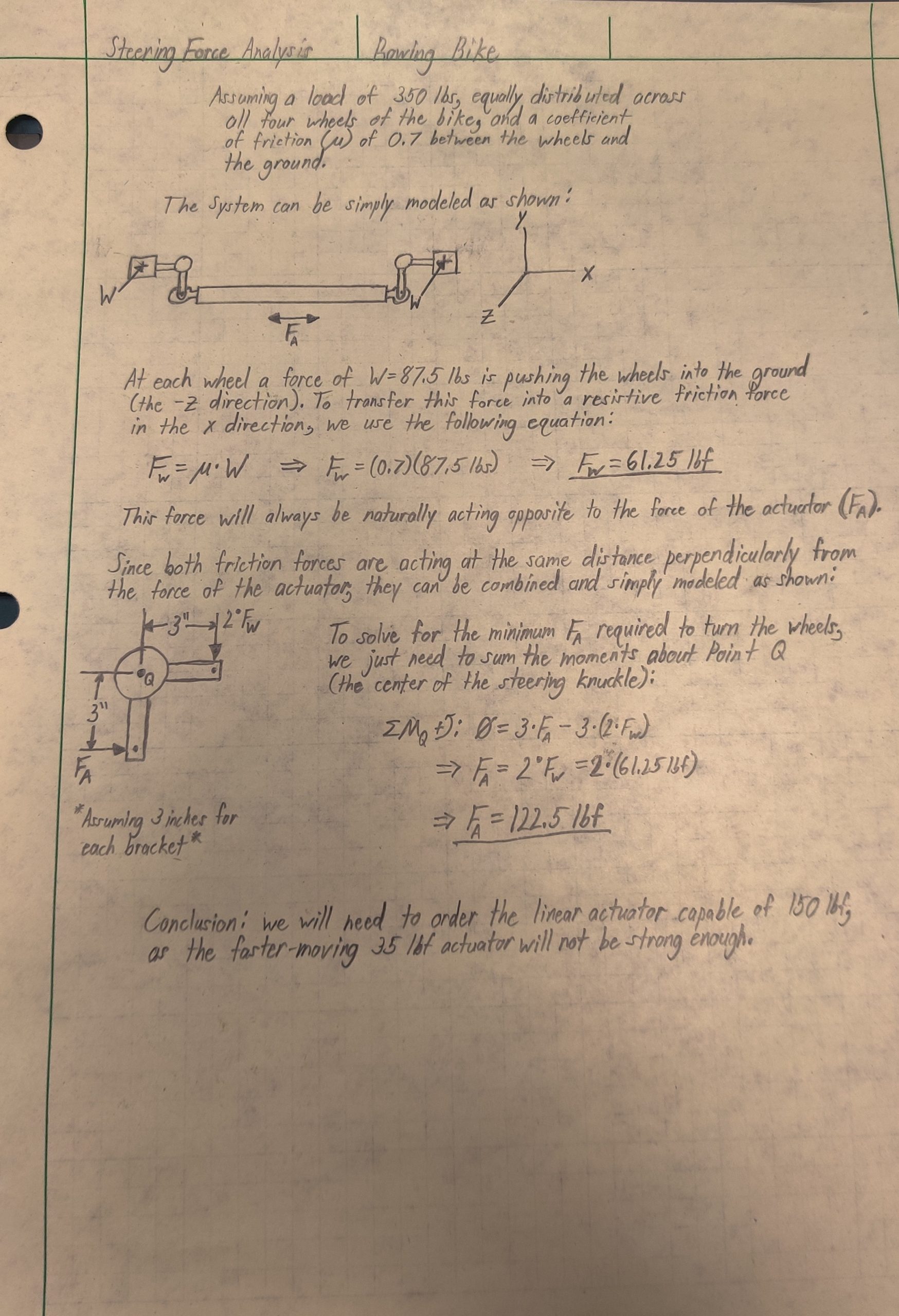
The steering will be driven by a Firgelli electronic linear actuator, which has a 150 lbs load capability and a 6 inch stroke. The stroke will allow for a 30 degree steering angle to the left and to the right. The actuator will drive a 22 inch tie rod, which in turn will drive the steering knuckles and turn the wheels. The actuator will be operable by two separate wireless remotes, one of which will be mounted to the handlebars and the other will be held separately from the bike.


The initial engineering analysis was over the frame. Using some base measurements from the old frame and adding some new designs we applied a load of 800 lbf directly to the seat and looked for the areas with the most deflection. With this critical points recognized we added supports where needed. Using the engineering analysis we were able to develop a stronger and more robust frame.
Seen in the photo is our second engineering analysis.
The frame started with raw materials, 0.065′ wall and 1′ od. Using the cad design of the frame on solid-works we were able to take all the measurements needed for the tubes and start the fabrication process. We used the tools in the machine shop along with a few specialty items from the formula shop to cut and notch all of the required tubes. Once all the tubes were cut out we began to weld the bike together in sections and eventually had a complete assembled frame.
Building the drivetrain started with machining the input shaft to press-fit tolerance(+0.0010″ diameter for i.d. of bearing) of the one-way bearings. Then, collars needed to be made to press-fit tolerance(-0.0010″ i.d. for the 10 different bearings o.d.). For the collars that were made to fit the bearing o.d a boring tool had to be used to bore out the inner diameter of the rings. Once, the collars for the one-way bearings were machined the rods that transmit force from the handle bar’s pushrods to the one-way bearings had to be cut and welded onto the collars.
