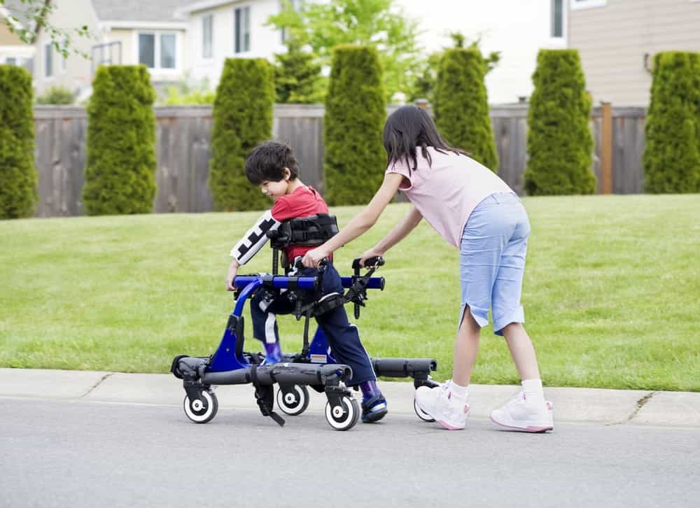
The boy has weakness in his knees and lower body. There is also a concern for his balance while walking. The mobility device will need to be able to support his lower body, while also allowing him to walk at the same time. The device will need to receive input from the boy’s arms and upper body, as they are strong and can assist in his movement. There will also need to be a feature allowing for the boy to rest his legs when tired. The mobility device will need to be adjustable with age and allow for “all-terrain” (indoor/outdoor) usage. A narrow design is desired, as well as a mechanism that can fold away for storage.
Design Specifications
-Mechanism for input with arms to assist walking (Hand pedals)
-Support for lower body (seat w/ strap)
-Adjustable with age (adjustable bolts on handle/seat)
Background Research
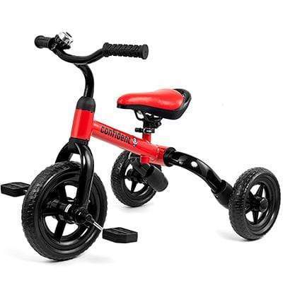
(Image 1) The 1st image is a “3-in-1 Trike” that can be modified to utilize our hand pedal mechanism.
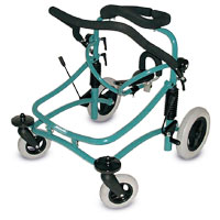
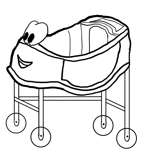
(Image 2) The family submitted this gait trainer. They said they liked the support this one provides, but wishes it was “cooler” and slimmer.
(Image 3) This is another gait trainer that highlights the ability for the parent to push the child around. There are also several safety factors, like the inclusion of pool noodles, that can be integrated into our design.
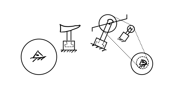
Concept Design 1
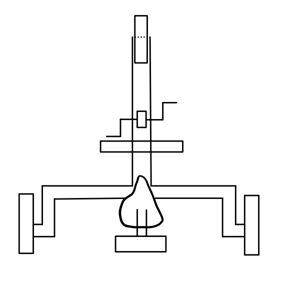
The first concept sketch is a modification of a tricycle. The pedals are moved to chest height to allow the child to pedal with his hands. The pedals drive the front wheel and the inclusion of a third movable gear allows the pedals to be raised and lowered as the child grows. The seat will allow the child’s feet to reach the ground while still supporting his weight.
Concept Design 2
The second concept sketch is an alternate trike modification. Instead of the hand pedals using a bike chain and gears to drive the front wheel, it uses a series of linkages. This is an attempt to reduce the bulk of the first gear design and allow the front wheel to pivot more freely. The pivot point of the linkage will be adjustable to allow the handlebars to raise as the child grows.
Concept Design 3
The third concept sketch is a modification of a Little Tikes car. It will be lifted to allow the child’s legs to extend fully. The seat will also be modified for additional support. The height of the car will be adjustable to allow for the child’s growth. The roof will be removed to allow the parents to easily move the child in and out of the “vehicle.”
Selected Concept Design
Our group decided to go with the “Crank trike” as it was the option that offered the most mobility. This design would allow for the boy to steer himself, while at the same time propelling himself forward with the hand pedal that drive the crank. The gear design would not have allowed the boy to steer himself.
Decision Matrix
Overview of Selected Design
After deliberation with the family and team members, we have decided that the inclusion of the mechanism enabling the boy to propel himself had more issues than benefits. We have decided to still consider the mechanism, but have opted for our main design to be non-proppelled, with the consideration of the crank still in the back of our minds during the final design. We have opted to use 2 of the handlebars shown below to connect with the tubing connector, that then will bolt into the clamp. This clamp can be mounted to the plastic handlebars via the application of epoxy. These two handlebars will come down to the left and right of the boy at around the hip level. The boy can hold onto these while walking to help support his legs. This design will allow for a limited range of steering, but the support of the bars is the main priority. Additionally, 2 torsion bars will extend parallel to the original handlebars to provide support for the load incurred by the fabricated handlebars.
For our backrest, we have decided to purchase a backrest on Amazon that can easily be modified to fit our design. We will remove the current clamp that is meant to attach to the seat and bend the rod to the desired angle to ensure the backrest is vertical to support the boys back and lower region. The same attachment will be used for the backrest as is used for the handlebars, except instead of epoxy a weld can be used for metal to metal transitions.
Our new tricycle includes a prefabricated bar in the back to allow the parents to push the child from behind as well as footrests that he can use when he is tired. We will continue to look for ways to incorporate the crank mechanism to drive the wheels, only if the family thinks this is a priority.
Engineering Analysis 1
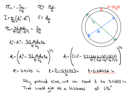
This analysis uses allowable normal stress developed in our handlebars to determine the thickness needed for our tube diameter. The flexure formula is used to find the moment of inertia required of our tube. With our design calling for 1″ diameter, the unknown variable of the inner diameter was found. This result yielded the thickness required for our tube to stay in the elastic region and not sustain any plastic deformation.
This analysis uses force equilibrium to determine the moment created by the boy applying a load at the end of our handlebars. This moment would then be transferred to the torsion bar and allowed us to realize that we needed to increase the diameter of our torsion bar.
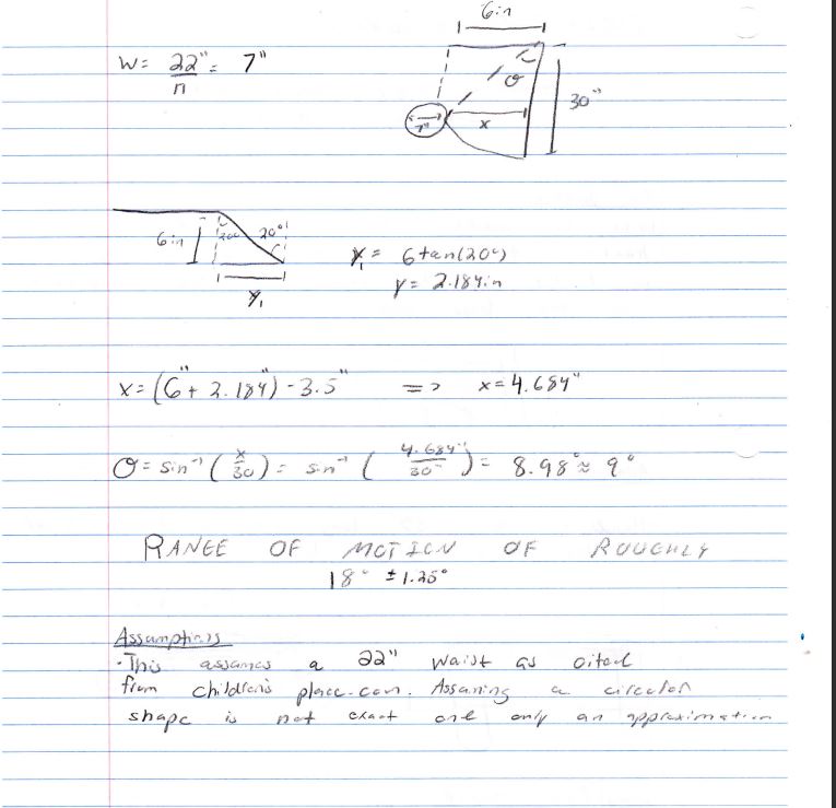
The goal of our third analysis was to determine the degree of rotation that our extended handlebar would allow. In a typical tricycle this is not considered a problem as the operator has a full sweep of motion only limited by the arms of the user. Our design has handlebars that run parallel with the length of the trike. This means that when the boy turns the handlebars, there is inevitably an angle in which the body of the boy impedes further rotation of the handlebars.
The angle allowed was calculated using geometry and trigonometric identities to find this angle. We assumed a conservative waist size using national averages. This assumption is reasonable as the family informed us that the boy was petite. Using this, along with the length of the extended bars as well as the length of the original bars, a triangle was able to be formed and the angle of rotation was able to be calculated using the sin(x) and tan(x) functions.


