college of engineering white

Feeding Tube Supports

Abstract

Our client has two children that both have medical issues. These issues require an apparatus that will help teach both of them to walk and encourage motor development. One has issues with maintaining posture, and the other requires a feeding tube holder and the ability to encourage her holding her own weight up. The solution that we came up with will be combination of multiple existing technologies that will fill theses needs for both children. We will combine some sort of walker support with a seat that will be able to support both children.

Wyatt Mabry Brian Fike Alex Gross Garrett Davis Aaron Gray

Problem Statement

The client needs a walker type apparatus that can accommodate two children that are both 18 pounds and 27 inches tall. There also needs to be a feeding tube bag and back support. Also we need to make sure it is comfortable for the girl with a feeding tube mount when looking at how the children will be held inside said walker. Along with these constraints we also need the ability for the children to comfortable grip some sort of handles at a comfortable height of about 15 inches from the ground.

Design Specifications

  • Needs to be able to be used by 27 inch tall children.
  • Support weight of at least 35 pounds.
  • The walker must be adjustable for the children to grow.
  • There must be a handle grip roughly 15 inches from the ground for the children to hold on to.
  • There needs to be back support for the boy with cp.
  • Needs to have the ability to mount feeding tube motor and bag for the girl.
  • No frontal compression when supporting girl due to feeding tube in stomach.
  • The walker should have some visual and/or interactive stimulation to keep the children interested in using the device.

Background Research

The base of our clients’ need is a walker of which there are many varieties. One idea was to essentially combine a walker frame with a baby bouncer. With this idea, the frame and seat would support some portion of the child’s weight while still allowing the child to move around using their legs. We plan to also add a hook to the upper portion of the frame as a way to support the girl’s feeding tube materials. Our main challenge will likely be designing a seat that supports some but not all of the child’s weight while maintaining the walker’s balance and allowing for the child’s movement.


Concept Design 1

This concept is a modified gait trainer with back support and feeding tube mount.

Concept Design 2

A walker frame with a small, round seat with leg holes. The seat would be supported with surgical tubing to allow the seat to support a portion of the child’s weight. There is a hook attached to the back of the frame in order to hold the feeding tube materials.

Concept Design 3

This has a walker frame where the seat has a hard back with a harness in order to help support the back of the child who needs it. This seat would be attached to the frame with surgical tubing to allow for the seat to partially support the children’s weight.

Selected Concept Design

DesignProsConsDesign 1

  • Already Proven
  • Meets Most Needs
  • Requires Minimum Modification
  • Sized Accordingly
  • Cost
  • Possible Mount Issues

Design 2

  • Fully Customizable
  • May be Cheaper than Design 1
  • Full Custom Fabrication for Frame
  • Time Intensive
  • Trial and Error
  • Needs Fully Custom Seat

Design 3

  • Cheap
  • Fully Choose Materials for Seat
  • Pre-built Frame
  • Proven Frame Design
  • Possibly Needs Reinforcement
  • Trial and Error
  • Possible Mount Issues

Upon our initial reviewing all of the considered candidates, we originally believed that Design 1 would be the most feasible and would require the least amount of modifications in order to fulfill the needs of our client. However upon further consideration, we decided that the customization offered by Design 2 would allow up to fulfill the client’s needs with far greater precision. Design 2 will require us to purchase a pre-made sling seat to accommodate our client.

Overview of Selected Design

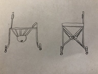
Our selected design will incorporate a fairly standard design walker for our frame with four castors on the on the legs, a custom designed back support, and a pre-made sling seat. The frame will be made of aluminum alloy tubing.

The seat would be the one shown below.
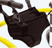
Feeding Tube Sling Seat.png

Describe Design Details

The frame design will have a U-shaped body with the front portion of the frame open in order to allow for the children to better interact with their environment. We will use four mounted brackets and pins to hold the seat to the frame while simultaneously allowing for easy removal of the seat in order to clean it.

The back support attached to the frame will give the children the trunk support needed to allow them to move around. It will be 3D printed and made of a plastic material.

The harness-style sling seat will help to support the children’s body weight while still allowing for a wide range of mobility for the legs. As the frame and many of its components will be made of an aluminum alloy, the frame will be more than strong enough to support any stressed the children will exert on it with normal use.

There will be a raised hook mounted to the frame in order to hang the feeding pouch on when the feeding tube is in use. The feeding tube pump will be able to be mounted and removed from the frame as needed.

Engineering Analysis 1

This is the mass analysis of just the frame. Using this analysis, we believe the entirety of the completed design should weigh approximately 10 pounds.

Engineering Analysis 2

This analysis uses a 200 pound point load. The material chosen for this pin is structural steel. The pin is considered fixed at the end with the larger diameter while the other end is left free. The color-based scale shows where the stain would be at the maximum and minimum values.

Engineering Analysis 3

This analysis uses a 200 pound point load downward along the y-axis. The material chosen for this tube is an aluminum alloy. The tube is considered fixed at one end and free at the other end. The color-based scale shows where the stain would be at the maximum and minimum values.

CAD Drawings

Bill of Materials

Document Fabrication Process

1) Aluminum tubing and brackets were cut in the shop and holes drilled to allow for height adjustment.

2) Our back brace was custom designed and 3D printed.

3) Foam padding was glued to the back brace for comfort. Nylon straps were also sown around pre-determined hole on the back brace to allow for trunk support.

4) Our frame was welded together in the shop.

5) We attached our back brace to the frame using a CNCed bracket and attached the seat to the frame.

6) After determining that everything was in place, our frame was painted.

Testing Results

Instructions for Safe Use

Do not use the device unless supervised by an adult that has been fully understood the safe use of this product.

  • To adjust height of walker frame remove all four clevis pins on the vertical bars, raise or lower top half of frame as needed, and reinsert the pins into the pre-drilled holes. Ensure all pins completely lock into place.
  • The height of the feeding tube support bar can be adjusted by removing the single clevis pin from the lower portion of the frame, raise or lower the support bar as needed, and reinsert the pin into the pre-drilled holes. Ensure pin completely locks into place.
  • The placement of the back support may also be adjusted by removing the two bolts attaching the walker frame to the bracket attached to the back brace. In order to remove these bolts use the provided Allen wrench to loose and remove the bolts being careful not to lose the nuts that are also attached, raise or lower the placement of the back brace as needed making sure to line up the holes on the walker frame and bracket, reinsert bolts and hand tighten nuts onto the bolts, and tighten the bolts using the provided Allen wrench.
  • To use this walker, unstrap seat and place child into seat. Strap Velcro portions of seat snugly around lower waist. Clasp the two nylon straps on the back brace around the upper and lower portions of the torso for trunk support.
  • Adjust nylon straps on back brace and seat as needed for comfort.

Project Summary/Reflection

Throughout our time working on this project, we gained experience with the tools and machines within the machine shop while also learning about the processes involved with designing and fabrication of a product. We worked together as a team in order to coordinate individual goals and timelines. Scheduling around a group of five can be difficult, so we tried our best to stay in communication with one another and keep each other updated on our progress. As we completed our individual tasks, the project as a whole came together and took form. When delivering the completed walker, the family seemed to be quite happy with the final product and the children seemed to have had little trouble with using the walker as intended. It was very rewarding to put our knowledge and skills together in order to try and better the lives of these children.

Semester