
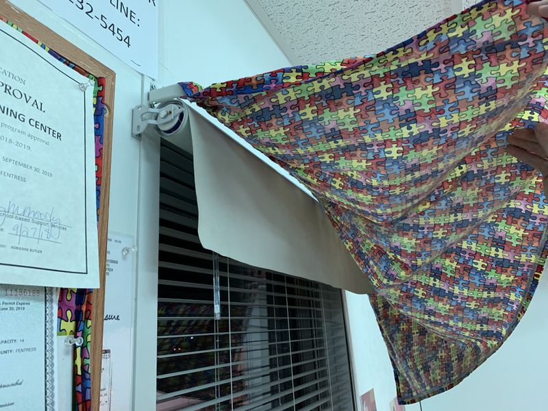
The Early Learning Center in Jamestown,TN is a school for children with special needs that nurtures children in the age range of 18 months to 3 years old and handles no more than 8 children at any given time of the school day. The faculty of the school have voiced their concerns about intruder drills and how, in the event of an emergency, it is not efficient for the limited amount of staff to control and move the small children from the main room into their “hiding area” in the closet of the bathroom, all while trying to get the blinds to drop down, and twist shut on the 5 windows that could reveal the children and staff’s location if an intruder were to look inside. There is a need for a faster system of lowering the blinds and twisting them shut at the flip of a switch. Also, the faculty were concerned about both of the 2 doors in the building that are poorly tinted in order to attempt to conceal the inside of the school. In the event of an emergency, these 5 windows and 2 doors would each need to be covered (using automated blinds, drop-down curtains, or some combination wired to a single switch) in a matter of seconds.
The Early Learning Center in Jamestown,TN is a school for children with special needs that nurtures children in the age range of 18 months to 3 years old and handles no more than 8 children at any given time of the school day. The faculty of the school have voiced their concerns about intruder drills and how, in the event of an emergency, it is not efficient for the limited amount of staff to control and move the small children from the main room into their “hiding area” in the closet of the bathroom, all while trying to get the blinds to drop down, and twist shut on the 5 windows that could reveal the children and staff’s location if an intruder were to look inside. There is a need for a faster system of lowering the blinds and twisting them shut at the flip of a switch. Also, the faculty were concerned about both of the 2 doors in the building that are poorly tinted in order to attempt to conceal the inside of the school. In the event of an emergency, these 5 windows and 2 doors would each need to be covered (using automated blinds, drop-down curtains, or some combination wired to a single switch) in a matter of seconds.
Requested From the School Faculty
•Blinds must be able to stay above window and drop/twist shut at the flip of a switch
•Blinds must be tied in a way that the string is out of reach of the children
•The system must be reliable in the event of an emergency
Engineering Leeway
•Type of blinds/sunshade for the windows and doors does not matter, as long as immediate concealment is possible and they stay out of the children’s reach
The following link will take you to a page showing the window and blinds setup that the Early Learning Center already has in place:
https://www.flickr.com/photos/ttu-eime-autowindowshades/
The following are measured dimensions of these windows and doors:
•Inner window sill length – 29.25in
•Blind length – 53in
•Door sill length – 36in
•Door Height – 82in
•Door window width – 30.5in
There are 3 windows in the main room, 2 windows in the office space, and 2 doors, all of which need to be covered in the event of an emergency. Some technology that already exists that would help out tremendously is motorized blinds/shades technology that are readily available to purchase off of the internet. Professional motor/shade systems can range from $60-300, and individual motors can range from $120-$150. As you will see in our “design concepts,” we have the option of designing our own mechanism to twist shut and raise and lower the blinds that already exist in the Early Learning Center, buying individual motors and attempt to get them to work with the blinds that already exist, or buy the motors and new shades that roll down without the need to twist them shut. As of now, there are many different options, and our group has not decided which is the best option. Designing a new mechanism/motor system could prove to be very challenging for us, and using existing technology would most likely be more dependable. Also, having to allow time for the blinds to be twisted shut adds unnecessary time to the overall lockdown process.
Design Concept 1 consists of purchasing automated blinds and wiring them to a switch within the safe room of the daycare. This would result in completely replacing the current blinds that are being used.
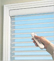
Option 1 aims to use a motorized version of your standard blinds. This specific model allows you to raise/lower and open/close the blinds with a handheld remote.
The 2nd option is to order motorized blackout curtains. With this design, you can raise/lower the curtains, however, you lose the open/close function.
Option 3 implements the concept of motorized cellular shades. Cellular shades are a window covering used to block or filter light and insulate windows to save energy.
One major benefit of ordering manufactured motorized blinds is dependability. Motorized blinds are designed for the “motorized” feature to be the main function, therefore, they serve as a more reliable option over the following design concepts. Another positive to these blinds is that no modifications have to be made to the blinds to acquire the motorized function. This is much simpler than modifying the current blinds. However, the cost range to purchase motorized blinds is significantly higher than if we were to purchase the motors and construct this feature ourselves.


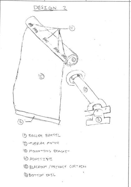
Design Concept 2 uses a tubular motor to create a custom set of automatic blinds. This design concept uses a new set of blackout or privacy curtains to attach to rolling barrel. The rolling barrel is rotated by an electric powered tubular motor.
The above schematic shows how a tubular motor works. They are designed to rotate the adapt wheel while the motor stays completely in place, thus creating a torque and rotating the tube. Tubular motors come in all sizes and are typically electrically powered. In our case, we would be using a 12V motor with a 30mm tube.
Design 2 shows the tubular motor being placed into the rolling barrel. The rolling barrel and motor will be mounted above the window using mounting brackets. The blackout/privacy curtain will be attached to the rolling barrel using adhesive. A bottom rail will be attached to the bottom of the curtain to help straighten the blind and allow for an easy rolling back up of the blinds.
Many tubular motors come with the ability to connect to a remote control. Ideally, all curtain motors will be connected to the same remote and can be lowered at one click of a button. This remote will be mounted using a remote mount in the location of their safety zone. The design of the remote mount can be seen below.
This design concept is a solid option because it is much more cost effective than Design Concept 1, but still has the reliability of motors used by manufacturers of automatic shades. In addition, the assembly process seems to be fairly simple with very few needed parts.


Design Concept 3 uses modifications to automate standard blinds already present in the classroom. There are two parts of the blinds that must be automated, the tilt wand and the lift cord.
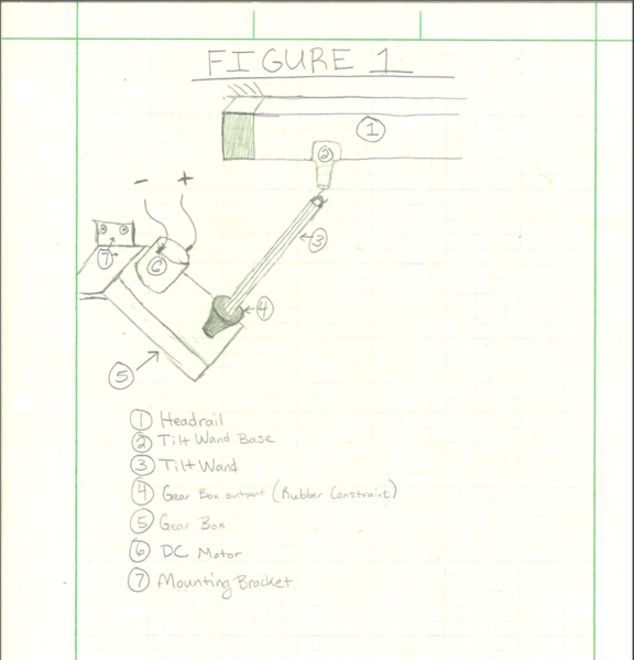
Figure 1 shows the setup for automating the tilt wand. DC motor input from a microcontroller causes clockwise or counterclockwise output to the rubber constraint. Clockwise output will open the slats, counter clockwise will close the slats.
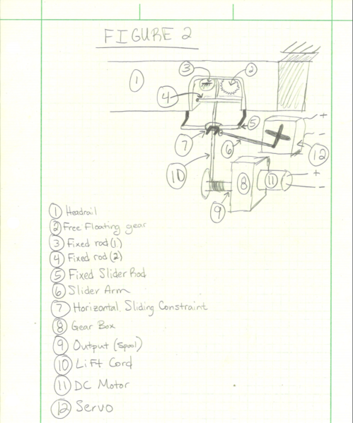
Figure 2 shows the setup for automating the lift cord. There are two inputs for a lift cord: horizontal and vertical. Typically, pulling the cord to the left releases the cord from the free floating gear. Vertical translation of the cord will then be reflected in the bottom rail of the blinds. Once the desired height is reached, moving the cord to the right will cause the free floating gear to catch the cord and lock up movement. The servo, slider arm, and slider constraint relationship acts as the horizontal input. The DC motor and spool relationship operates as the vertical input.
This design is less expensive than other options mainly due to the fact that the current blinds can be used, but it is much more complex than the other concepts. Its complexity could cause issues because there are approximately 7 windows that need to be modified and each one must be reliable in “code red” situations.
| Concept 1 | Concept 2 | Concept 3 | |
|---|---|---|---|
| Cost | 8 | 4 | 2 |
| Reliability | 9 | 6 | 2 |
With reliability being a huge factor in this project, concept 3 is not the ideal option. Concept 1 is most reliable, but is much more expensive. Concept 2 uses custom made blinds to lower cost, but maintain reliability. We are leaning towards option 2 for those reasons.
We have selected our design to be concept 2.
Required: 5 MorningRising 12V DIY Electric Roller Blinds (seen below) with 1 remote.
5 schedule 80 1.25in PVC pipes that are 32 inches long.
5 32x60in cuts of polyester fabric.
1 12V power supply.
The PVC will have a window height’s piece of polyester blackout fabric rolled on to it. It will then slide over the powered wheel on the shaft of the motorized roller and attach at the other end to the revolute joint of the iron mount. The iron mounts will be placed directly underneath the puzzle drapes covering the top of the window. This works well for a couple reasons. One, we are not pressed for space as we would be if we were to place the mechanism within the window frame. Two, the puzzle drapes will entirely conceal the mechanism. The electric roller comes with a remote that will be synced to each of the rollers. The user can use buttons on the remote to set the up and down boundaries. Once they are all synced together, all blinds should deploy or retract at the push of one button. As far as power supply goes, a room to which the children do not have access will house a concealed 12V DC transformer. Low voltage line will then be run through the ceiling to each window.
One of the mounts will go here, the other will go on the opposite side of the window
Here is a list of metric dimensions used in calculations:
| Motorized Roller | |
|---|---|
| Length | 0.280 meters |
| Wheel diam | 0.030 meters |
| Mass | 0.476272 kg |
| Motor Voltage | 12 V DC |
| Schedule 80 PVC Shade Tube | |
|---|---|
| Length | 0.8128 meters |
| Inner diam | 0.0325 meters |
| Outer diam | 0.0422 meters |
| Mass | .62586 kg |
| Circumference | .13258 meters |
| Shade | |
|---|---|
| Width | 0.8128 meters |
| Height | 1.397 meters |
| Mass | 0.46198 Kg |
| Thickness | .6604 mm |
Note: some dimensions were estimated using online data tables


static analysis of mounts and their stress
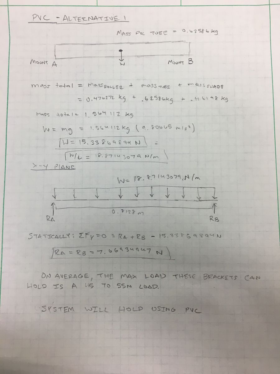

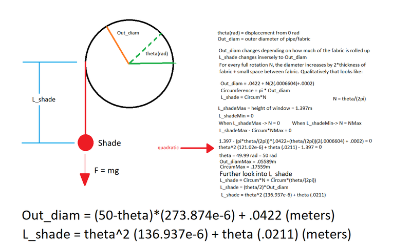
Here we look at relative motions of the mechanism. We can describe every movement as a function of theta, the angular displacement of the tube.
Two equations are particularly useful in this scenario:
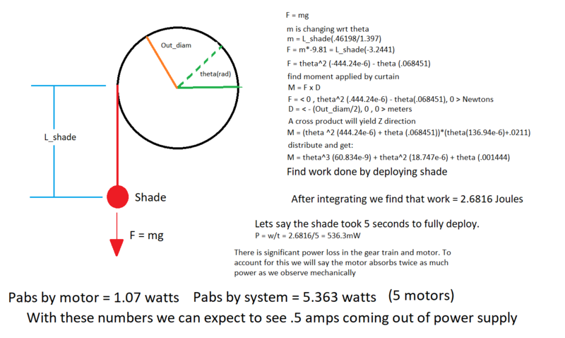
Now we take the equations we found in analysis 2 and apply them to forces, work, and power.
The goal here is to estimate the electrical power absorbed by all 5 motors for help in choosing a power supply.
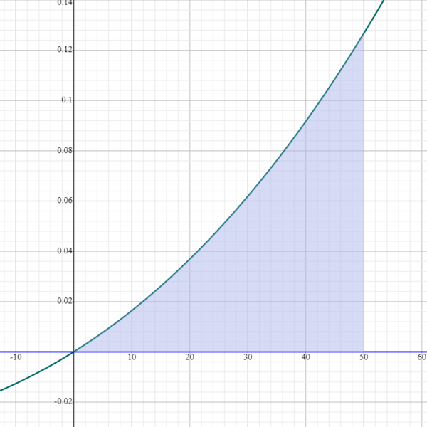
Below is the integration of the moment which yields work required to move the shade from up to down or down to up


The first thing we fabricated for this project was the PVC pipe. We had 2 long lengths of 1.25 in PVC pipe that we cut down to the exact width of the windows they were to be mounted in plus about 1 inch on either side. After that, we tried a couple different methods for fitting the motor shaft to the inner diameter of the PVC. The option we went with was duck tape, not for its stickiness, but because it could be added in thin increments until the output shaft fit tight to the PVC. Next, we secured the blackout fabric to the PVC with a series of small screws. That concludes the fabrication of the tubular shades.
We then needed a project box in which to hide connections between power supply, fuse, and output wires. We built the project box out of poly-carbonate. The box has a hole on the bottom for the power supply chord to enter, two holes on the right side for the fuse to come out then back in ( this way the fuse can be accessed without taking the box off the wall ), and 2 holes on top for the positive and negative output wires. Those wires are then run secured with staples and run into the ceiling where they are sent to each of the 5 motors.
One problem that we ran into when installing the shades is that two of the motors were placed in a room that did not have ceiling tiles. Our only option was to run the wire in the edge of the ceiling and wall which was perfectly fine by our client.
All electrical connections between wires were down with appropriately sized wire nuts depending on the size and number of wires being connected.
The window shade motors were tested in the machine shop successfully using the power supply and remote they came with when they were ordered. Each motor was fitted with duck tape in order to maintain proper grip on the inside of the PVC pipe, which the curtains will wrap around when they are not being used. The deliver process will involve simply installing each motors bracket below the existing curtains and then wiring each window shade motor above the ceiling tiles into a central housing. Click here to see a video of the shades being programmed/tested before installation.


The window shades are simple and safe to use. In order to raise and lower the curtains, all the user/teacher has to do is click down/up on the remote and the curtains will all automatically adjust simultaneously. No direct interaction with the shades is necessary other than with the remote. In the case that there is a short or the motors are overloaded, there is an 8 amp fuse down stream of the power supply. The load of the motors is about 4 amps while the power supply can push a maximum of 10 amps. If the 8 amp fuse is ever blown, the system should be inspected for failure before replacing the fuse. Before inspecting the system or handling the wires, ensure the power supply is unplugged from the wall.
After pressing up or down on the remote, the square button in the middle of the remote may be pressed to stop all actions.
This project was a great hands on learning experience for everyone involved. We were shown a side of real world engineering that schooling often does not show us. Watching a device go from dream to reality over a couple short months was a rewarding and impactful experience. Seeing the reaction on the face of school faculty to the shades deploying/retracting at the push of a button made all of the hard work and dedication worth it. Everyone was grateful and happy with the product we presented. We want to say thank you to school faculty at the Early Learning Center for help and support throughout the process. Thank you also to Dr. Canfield for all of the hours he puts in to make this experience possible. We hope this project continues to be supported for other groups for many semesters to come.