This project is about making a custom pool lift for a child with tracheostomy tube attached to her and to a ventilator. The family has previously been supported by the TEK program with a deck that allowed accessibility to the pool and several attempts on making a pool lift. Our group and another group have been tasked into working together to finalize a design and build a pool lift that fits the needs of the child. While designing this pool lift we need to make sure it is durable to outdoor elements and be able to safely lower and lift the child out of the water while the ventilator is safe from water damage. With working with the family and professionals we can build a perfect pool lift for the child.
A child with a tracheostomy who has a ventilator wants to use their swimming pool but due to the ventilator and the tracheostomy they have restrictions in physical activity. We were tasked to build them a pool lift that would be mounted to the deck that a previous group has built to help with the child’s accessibility with the pool. A custom pool lift with TEK will be cheaper than market options. This way we can make a lift that is specific to the needs of the family. The pool lift will allow the child to be lowered into the water and out of the water safely where the trach and ventilator will be safe from water. Also allowing the child to have fun in the water while also being safe. Navigating her physical limitations will be the biggest part of this project with the child not being able to be submerged lower than 12 inches. Making the goal to stay above 10 inches will sure her safety and she will be able to have fun.
Design a Pool Lift with specific parameters:
Options to use electric or hydraulic systems. The family prefers to use electrical so they can have a switch to move the lift. However we have to make sure the electrical box is waterproof so no damage will happen.
We need an comfortable and secured chair. A chair that has some attachments like footrest, armrest, seatbelt, and possibly a table to fold down for toys. Also it needs to support the child’s weight and handle weathering overtime.
The lift itself is very complex. We need to be confident in our structural analysis so the lift doesn’t break. It must support the deck, the arms, the weight of the child, rotation, lifting and lowering while the arm is stretched out.
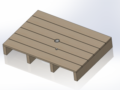
Need to learn on different ways to mount the lift to the deck. Either sandwiching two plates together and grounding the bottom plate to the ground or figuring out how to connect the two plates. This adds a tough challenge since most pool lifts are mounted to concrete, and this one is mounted to a wooden deck.

With Concept design one we plan on using the past project that made and adding some significant modifications to accommodate the bigger lift. The current lift is made from 4×4 tubing and is pretty hefty. To make this work we would add metal plates on the bottom of the foundation to do a sandwich method and mount the two plates together on the deck via bolting to the joist. Then we would use turnbuckle connected to steel wires and connect one end to a wind anchor screwed into the ground with the other end connected to the bottom plate.
This would help secure the lift from disconnecting from the deck and strengthen our load bearing analysis. With addition to the old lift, we would add a carabiner mounted to the lift allowing the family to place the ventilator in a safe spot. We also plan to upgrade the linear actuator to be stronger and allow the chair to swivel side to side.


Concept design two brings all of these same ideas above together with a slight change. We would downsize to 2×2 piping with changes the amount of support system needs to withstand the loads. It would make the lift lighter and the mounting easier. With a smaller piping we will be able to save money and use the old actuator, however will would need to purchase brand new material for 2×2 piping. There are many pros and cons with this decision, and we will look into the most cost-effective, safe, efficient design.

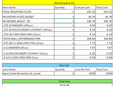
Our third design is more expensive than the rest. We want to buy a used pool lift and modify it to fit the wants of the family. While pool lifts are expensive it will allow us to focus more on the mounting side of the lift which the previous group had problems with. Adding electrical components using the previous groups electrical box and how they made the lift move.

Concept 3

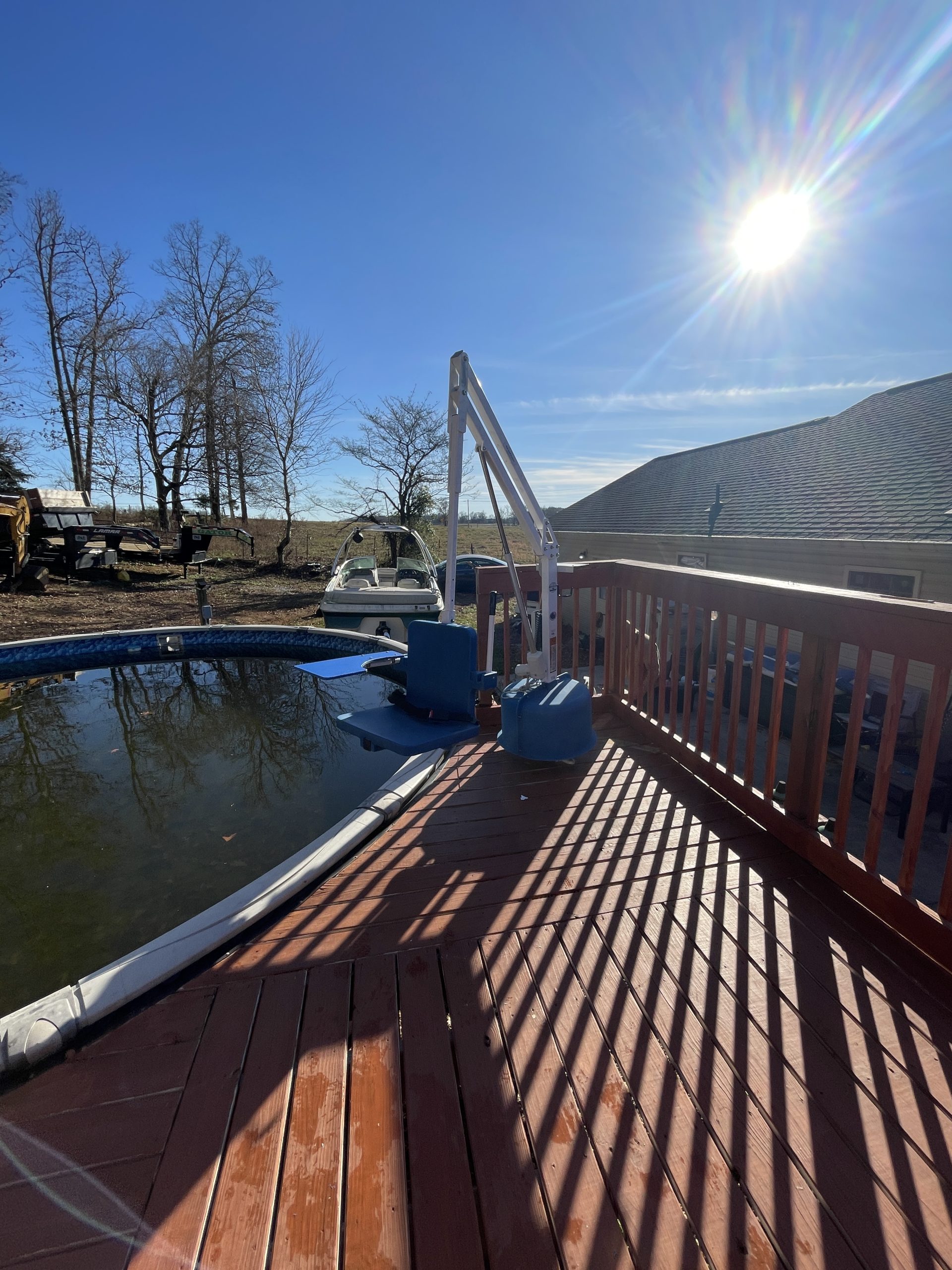
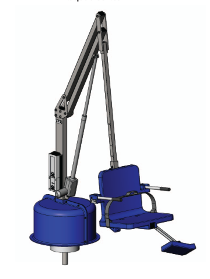
Concept 3 will consist of us buying a pool lift and modifying it to accommodate the needs of the child while also ensuring their safety. Because most lifts are designed to be mounted in concrete we will need to design a mount that’s compatible with the lift and the wooden deck. There will also be the need for modifications that limit the action of the lift to ensure the child is not submerged further than previously specified as well as not being able to rotate into the deck railing. After fully completing these tasks we will then begin looking into other customizable features such as umbrella mounting spot on the chair, possibly even completely redesigning the chair of the lift.
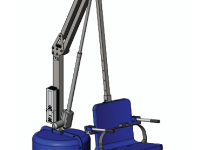
This pool lift supports a load/weight of 500 pounds. From the base of the lift to the seat of the chair, the lift fully extends to 5.76 feet horizontally. As is, the seat of the chair sits at 18” above the deck at a complete upright position and the vertical travel distance of the pool lift is 46”. This travel distance will be adjusted to approximately 34-36 inches to accommodate the needs of her trach and ventilator.
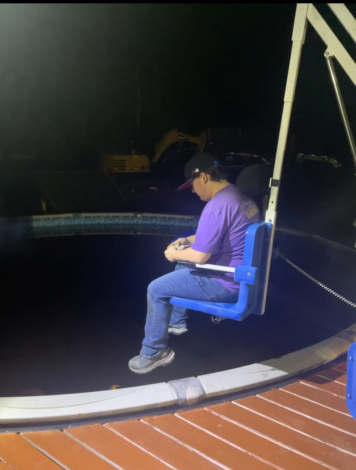
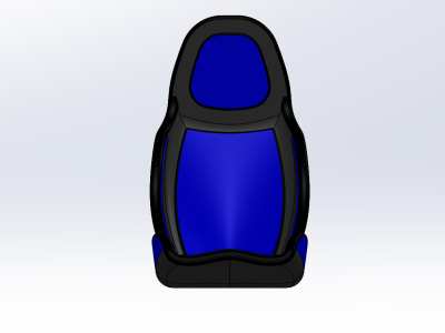
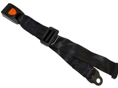
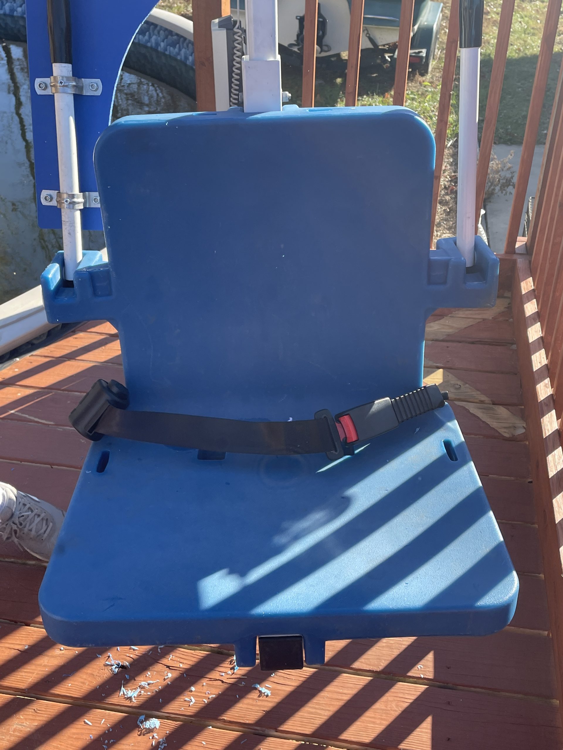
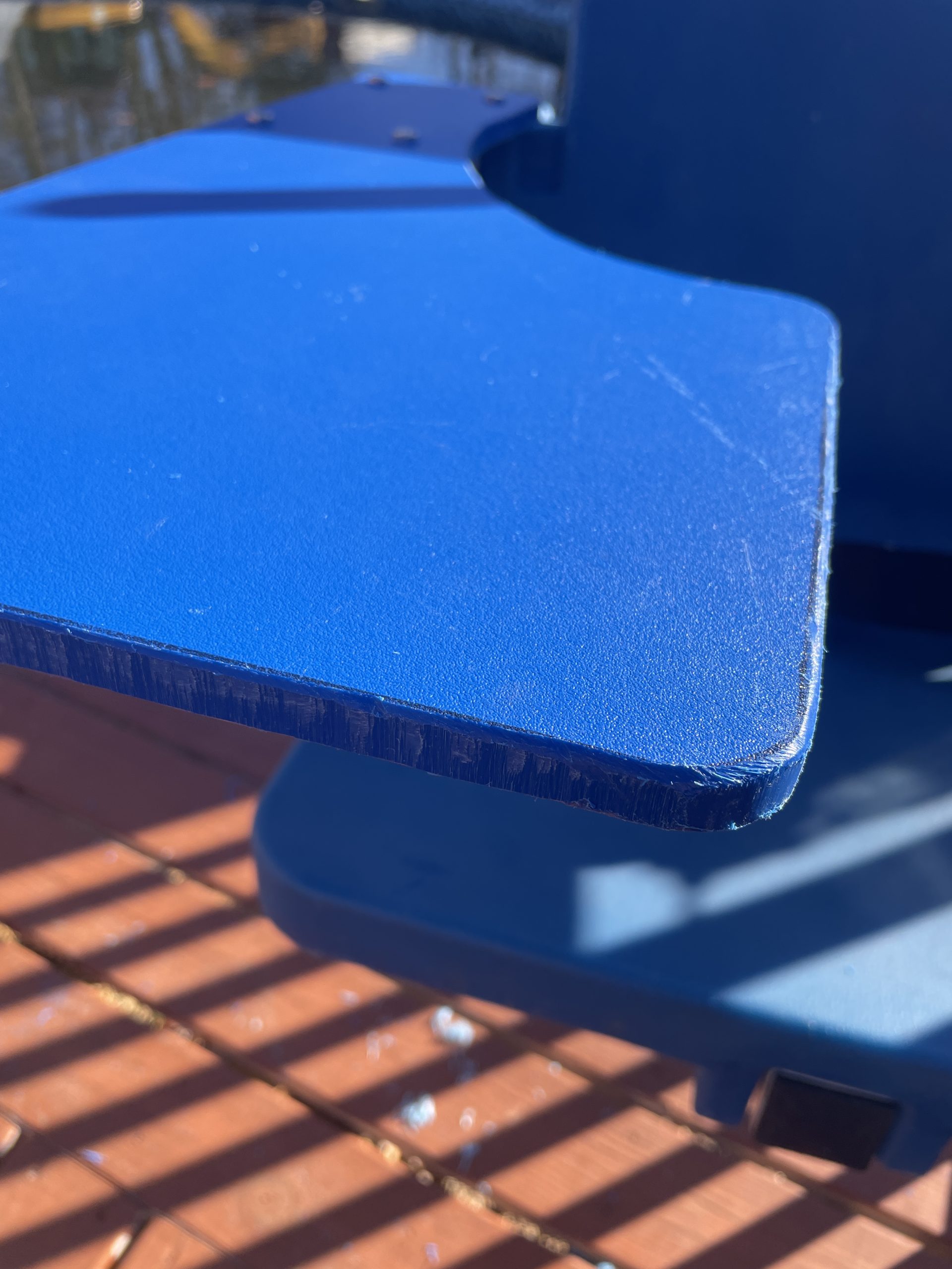
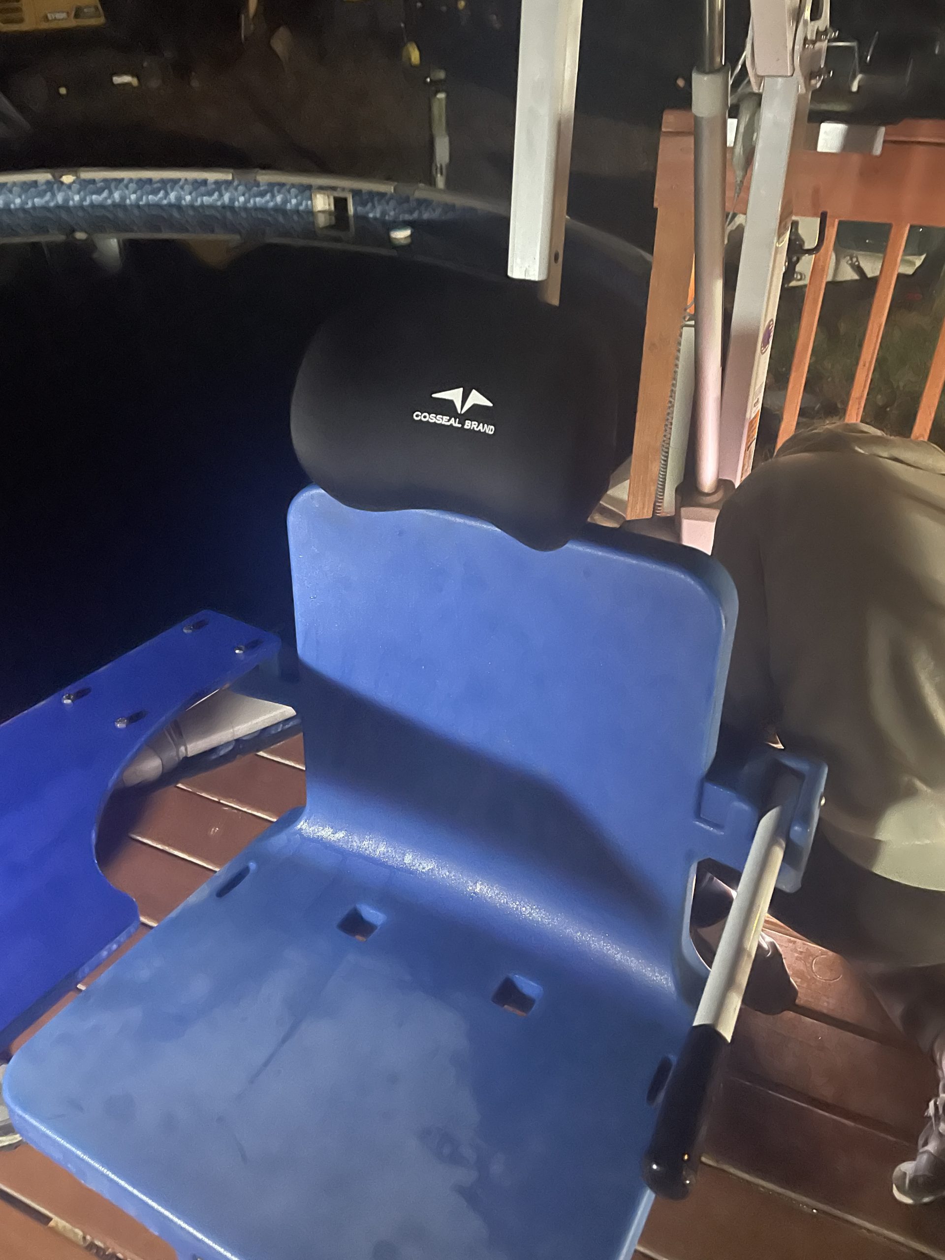
The newly designed chair has design specifications that cater to her needs, including a fully bracketed seat and backrest, keeping her from falling out on the sides, and a seat belt feature that secures the client to the chair. Notice the slightly reclined nature of the chair, further securing the client to the chair and preventing the chances of falling forward.
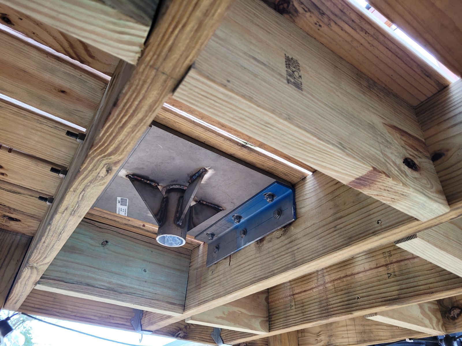
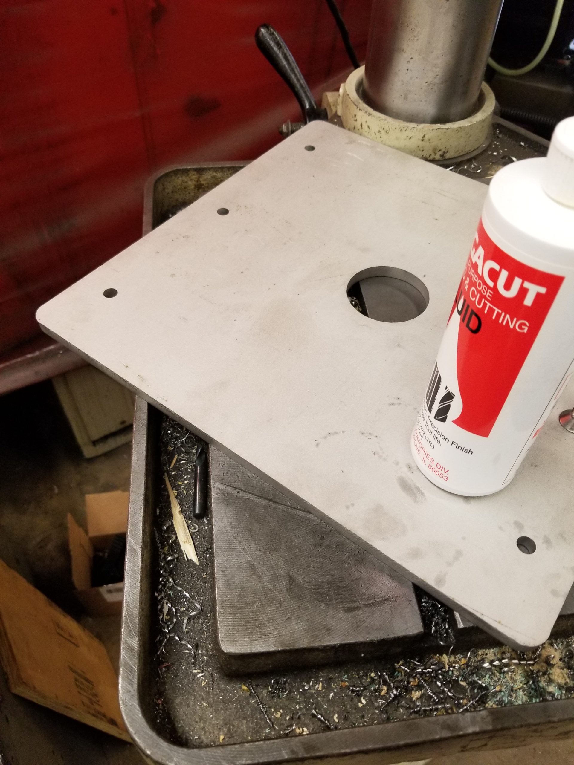
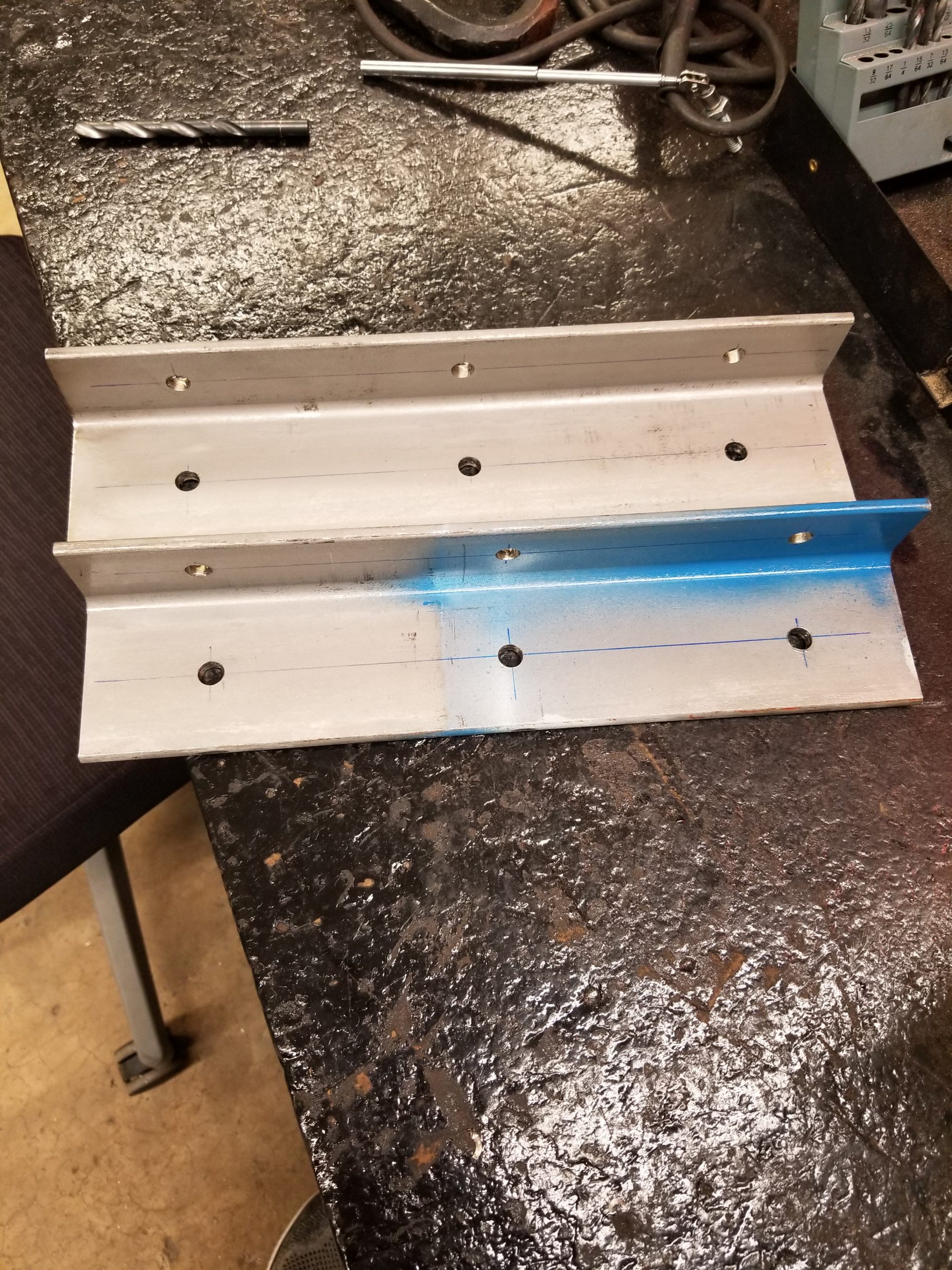
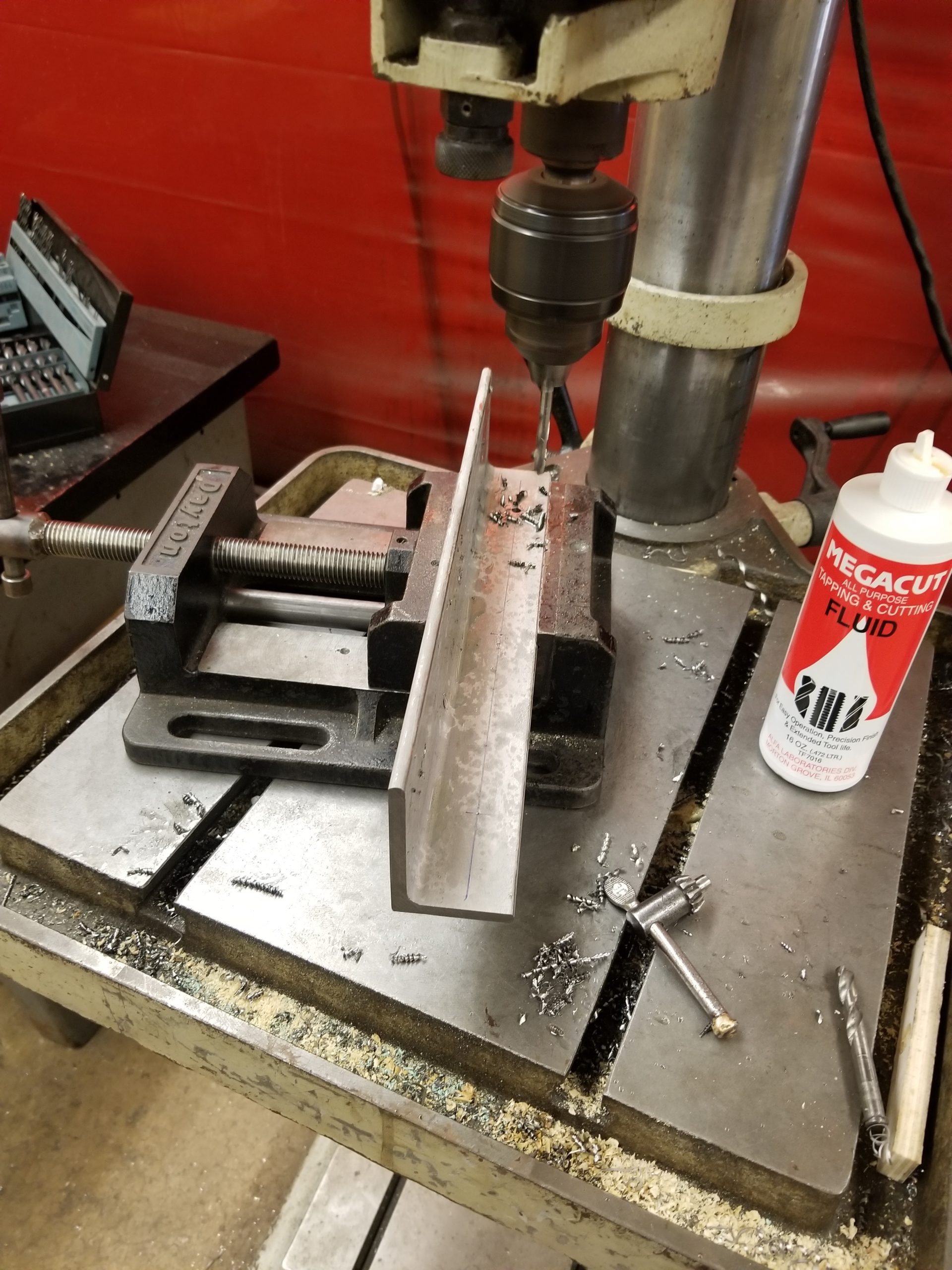
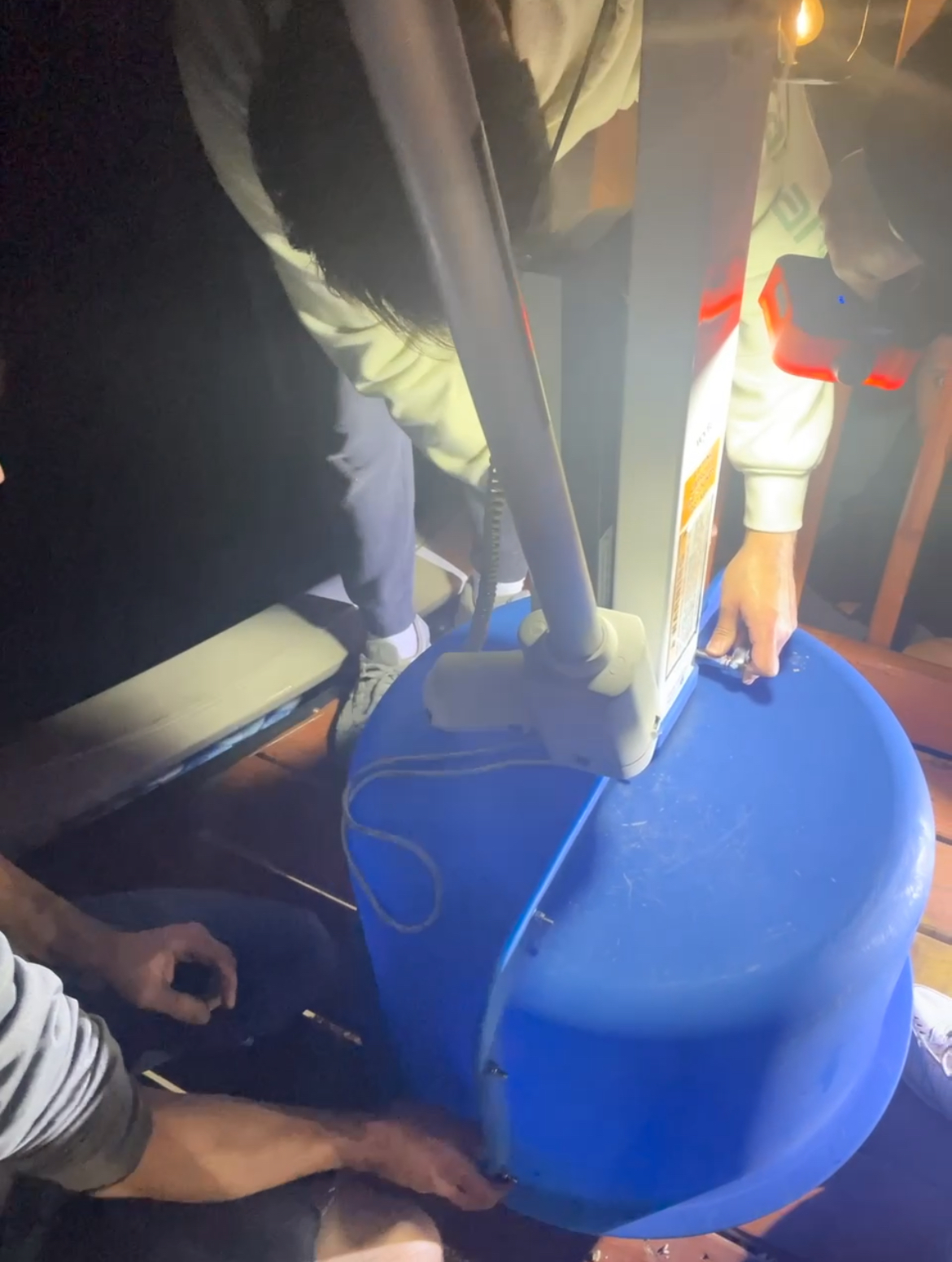
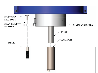
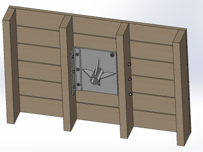
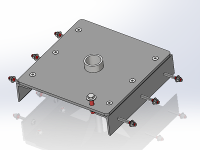
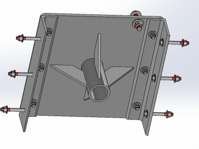
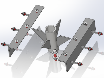
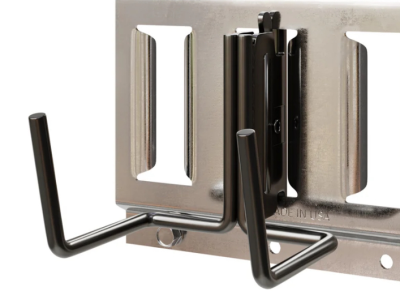
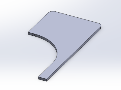
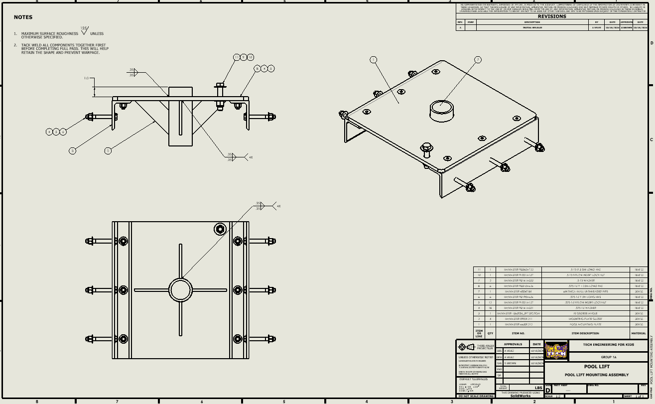
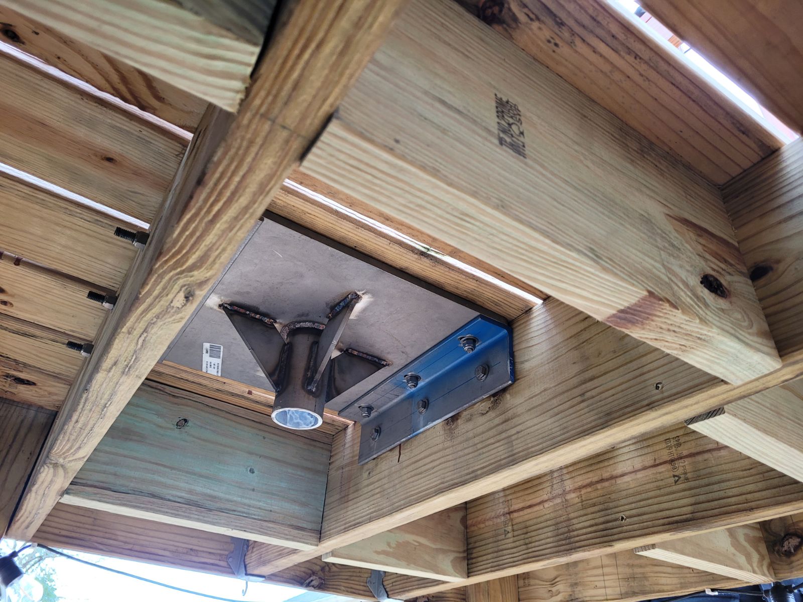
The post of the pool lift’s main cylinder will be fastened into an anchor pipe. The pipe anchor will be connected and secured to a plate underneath the deck. This plate is further attached to a 90 degree metal angle bracket fastened to the joist in place. The mounting features will be fastened and connected using washers, locknuts, and screws of various sizes.
For the chosen chair attachments, we decided to add a table onto one of the already folding arms, a mount for the trach and ventilator, as well as an umbrella for the trach and ventilator to lower the chances of it overheating.
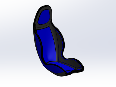
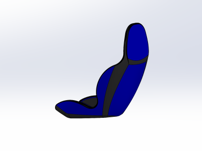
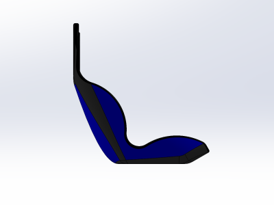
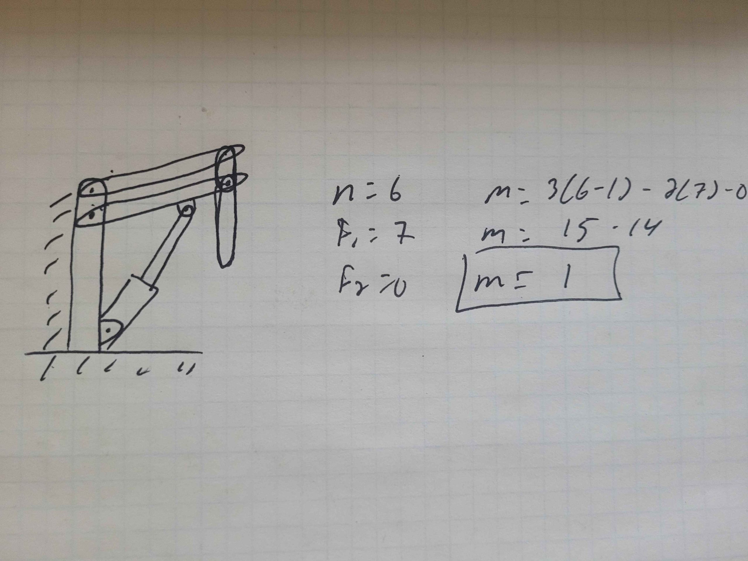
Here is our mobility analysis. As you can see on the motion gen we had 2 degrees of freedom due to the rotation point at the end of the top link but the lift doesn’t rotate at that point. Had to put some sort of rotation in order to show the movement. We have only 1 degree of freedom due to the linear actuator is only moving the lift up and down.
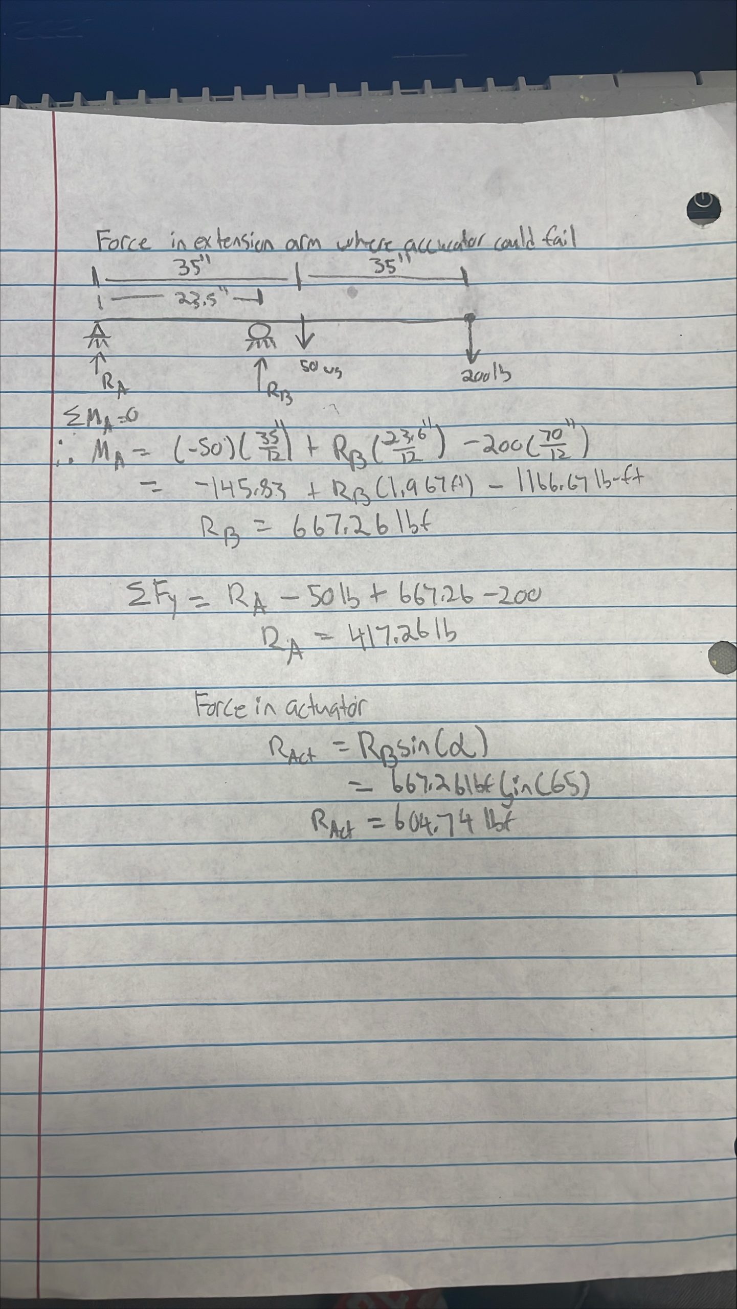
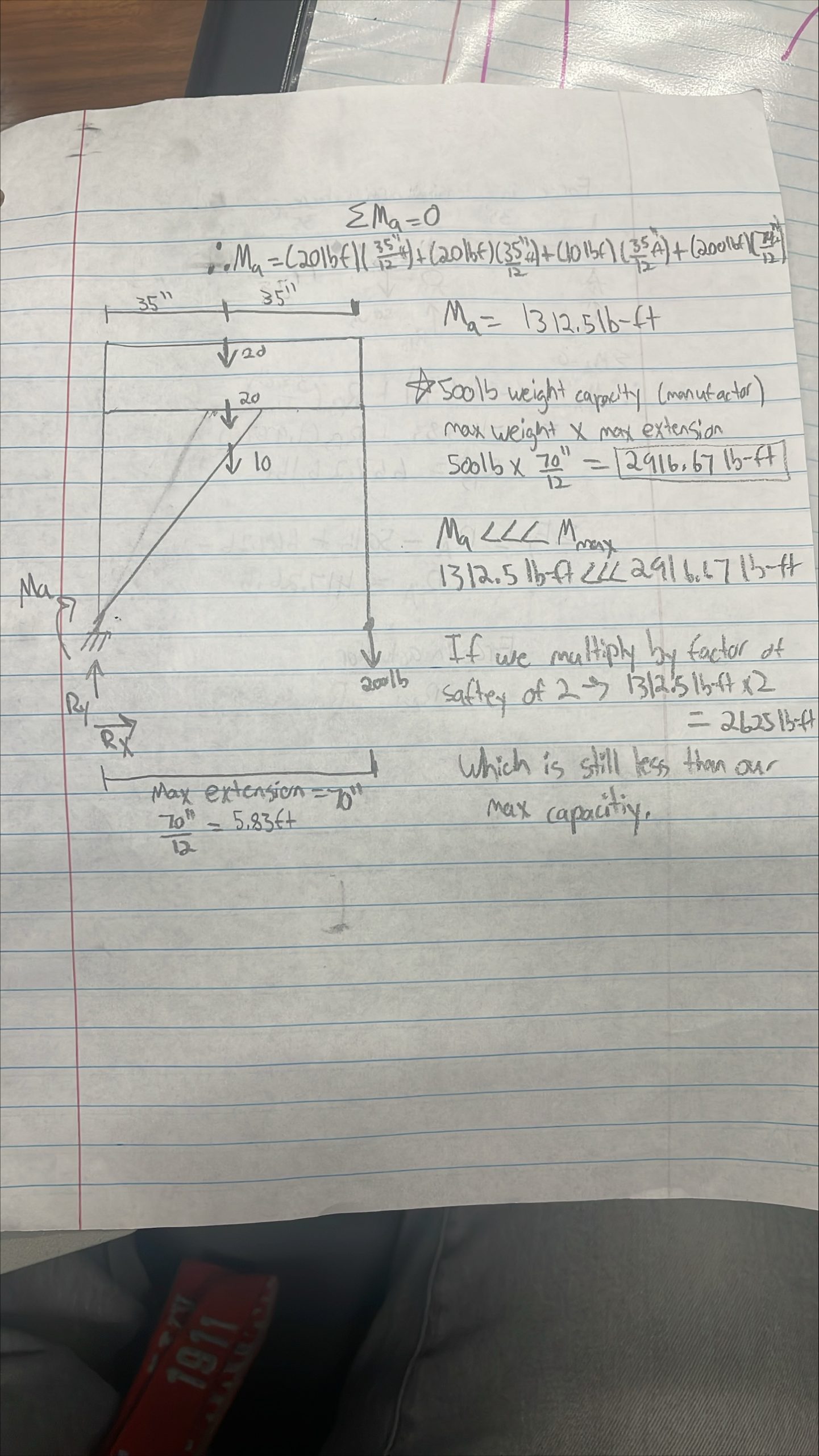
We performed manual calculations to find the forces acting within our system. We more than doubled load expected at the end of the lift to accommodate future growth of the child and additional components such as her trach and ventilator. For the induvial components of the bar, we considered a distributed load based on its length and weight per foot, simplifying it to a point load acting at the center of each member and a estimate of a total of 50 lbs. split up. Alot of our analysis were very similar to last semester team’s calculations due to the lift having some the same basic principles being applied. We also treated the lift as a static system to determine the forces and stresses. The first calculation was done with the lift positioned at 90 degrees, allowing us to observe how forces acted through each member and assess whether the actuator could support the weight when at rest. We then analyzed the lift in its lowest position (max set point), as this is where the actuator experiences the greatest force. Finally, the next set of calculations focused on the moment at the base of the lift to account for the torsional stress on the base plate and tube sleeve during rotation.
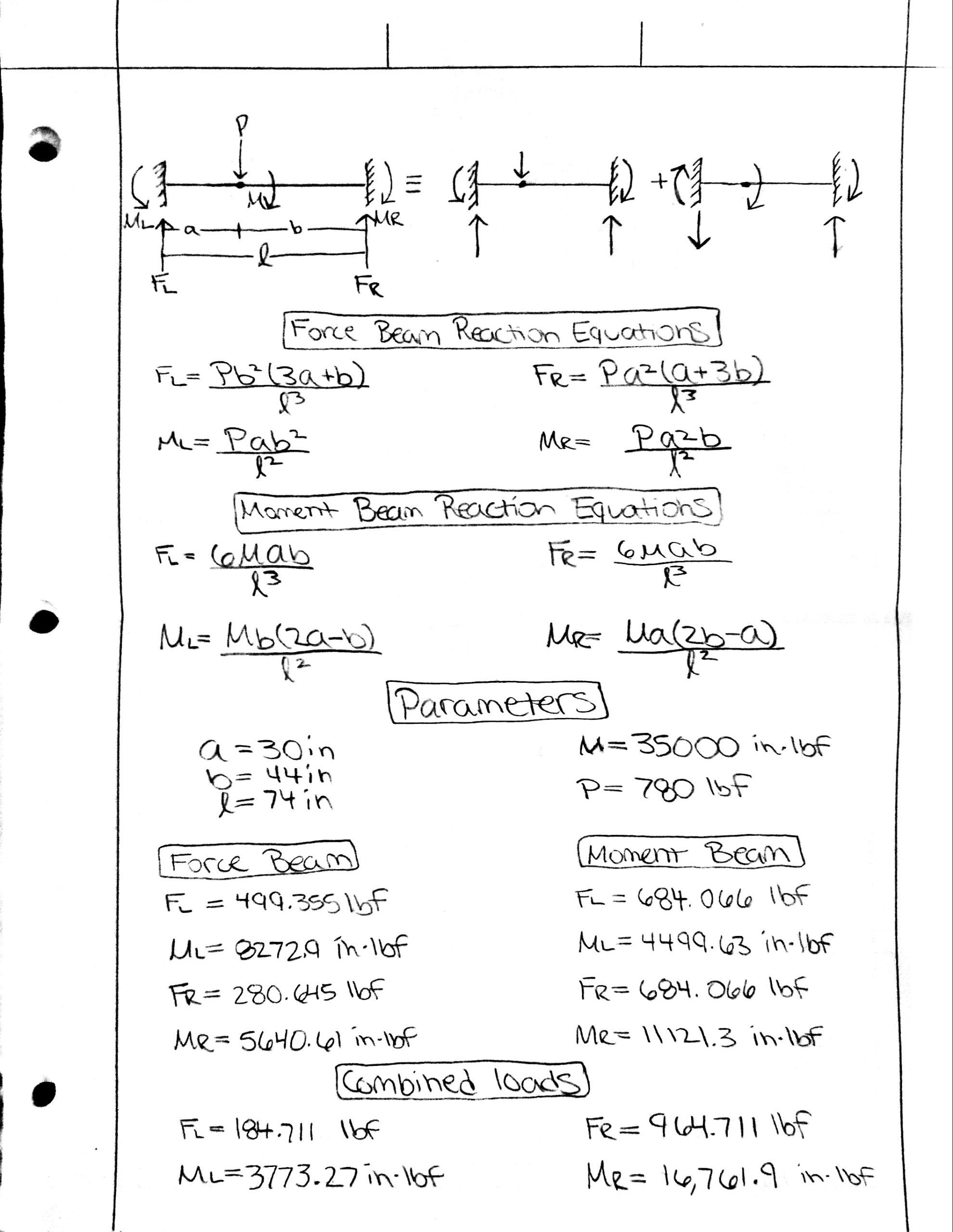
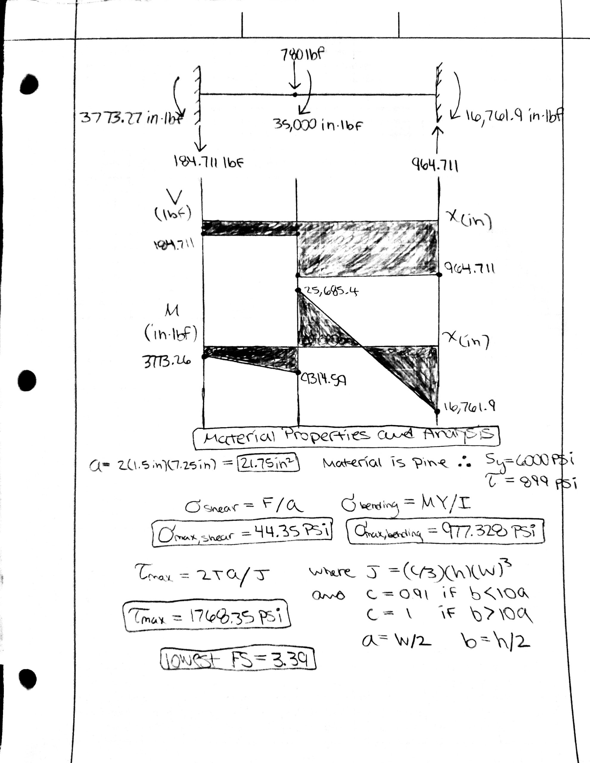
This analysis was to ensure the joist would be able to support the lift. Ideally another analysis would be done at the joist ends to ensure that the hardware used to mount the joist would not fail. This analysis used the loads found in the engineering analysis 2. From there we used superposition in order to easily find the reaction forces and moments acting at the joist ends. The equations used to determine the reactions were taken from a fixed-fixed beam reactions table. After finding the reactions and combining them into the resultant reactions we drew the shear and moment diagrams. The resultant shear and moments diagrams show the maximum shear and bending moments present in the joists. The maximum shear was 964.711 lbf while the maximum bending moment was 25,685.41 in*lbf. Another force to account for was the torsional force created on the joist when the lift is positioned over the pool. That torque is 35,000 in*lbf. Using the max shear, bending moment and torque forces we calculated the stresses created then compared them to the yield and shear strengths of pine. The lowest factor of safety of the 3 came out to 3.39 and this was due to the torsional stress. This analysis shows that the 2 joists we will use to mount the lift too will be more than strong enough to support even the heaviest of loads lifted by the lift.


10/25
10/29
11/8
11/13
11/15
11/18
11/20
11/22
11/25
12/4
12/5
12/9
12/12

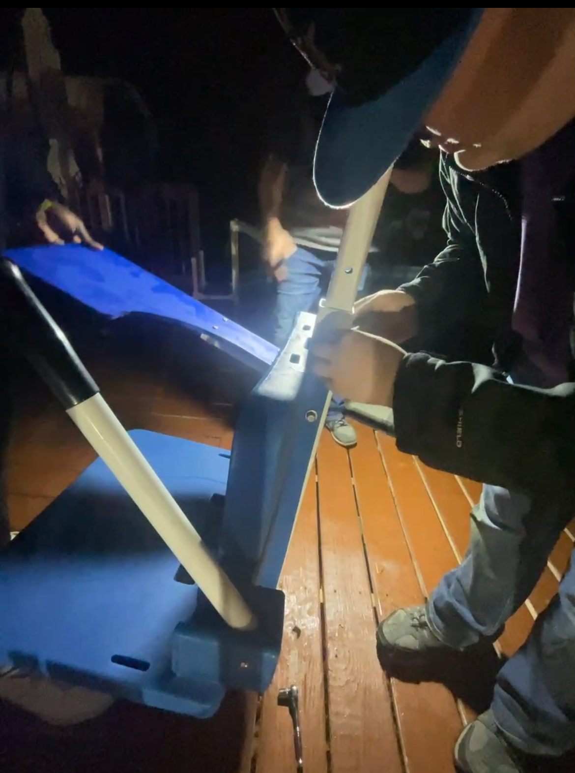
Here are safe instructions for using a pool lift for a child with a ventilator tube:
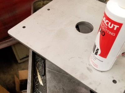
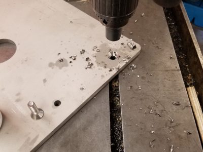
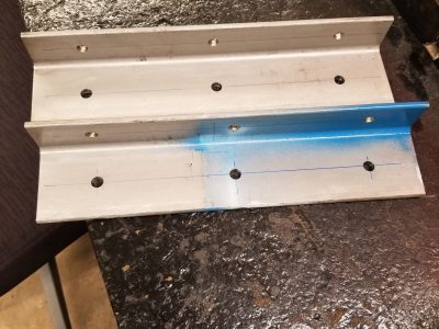
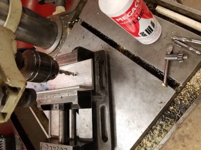
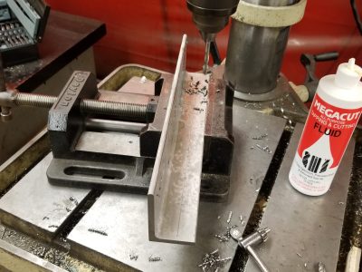
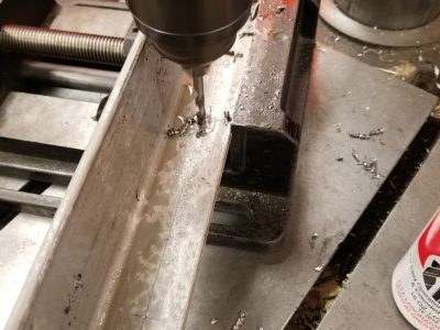
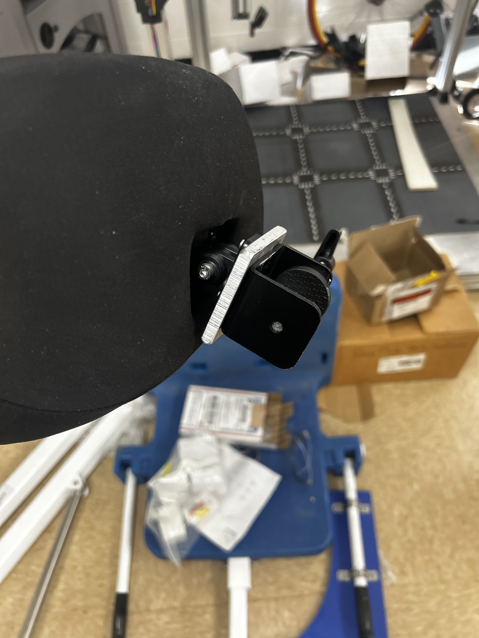
The pool lift project was a extensive project that required knowledge from multiple branches of engineering including problem solving, electrical engineering, manufacturing and structural analysis. Our project required us to construct and deliver a pool lift that could safely place a child into a pool. We looked through several designs and many different paths while weighing the pros and cons before deciding to purchase a lift and modify it to the child’s specifications. Once we got passed our analysis and research, we ordered the parts and began working on the project as soon as they arrived, as shown in documentation fabrication section. For our structural questions and problems, we went to Jeff Randolph who was very helpful with whatever was needed. For our electrical questions and problems, we went to Chris Mills who was very helpful with whatever was needed. Weekdays were spent working on everything we could while the weekends were spent reviewing what was done, assessing any problem that arose. We strove to find solutions and times group members could meet to work on revisions on the project such as the added table, headrest, etc. All of the fabrication could not have been done without the help of Jeff Randolph. He also helped guide us on many of the fabrication steps where we were unsure of like simplifying the headrest for the Childs needs and welding the plates together for us.