Our client is a three year old little girl born with Cerebral Palsy. Because of her disease, she has trouble controlling her muscles. The family recently found out she has been having seizures as well. She is now on a medication to stop the seizures, and this is helping soothe her muscles. However, the only thing that will calm her is her mother bouncing her. This is an issue because they have two additional small children. So, they currently have an automatic baby swing that helps to soothe her, but she is quickly outgrowing it. The family would like a larger swing that will allow them to switch out seats as she grows as well as roll from room to room to outside.
Carson Hampton
Joey Swindle
Sydney Bogard
Alissa McDougle
Problem Statement
Our client needs a swing to help calm her when her mother is busy. She is hard to soothe due to the shaking caused by her Cerebral Palsy. The swing should be able to move slowly while she eats as to not upset her stomach but still move faster for general use.
Design Specifications
1. Should support the child’s weight now and for the next few years
2. Strong supports so that it cannot be tipped over
3. Wheels to move over carpet and able to go outside
4. Must have a wall plug
5. Needs a low speed setting for eating as well as high for play
6. Able to swing side to side as well as front to back
7. Narrow enough to fit through doorways
Background Research
There are several similar products currently on the market such as swings, gliders, and rockers. The issue with these products is that they are aimed towards infants, so our client is outgrowing her existing swing. She is currently within the weight limit on these products but is exceeding in length. Therefore, there is no product on the market that will suit her now or in the future.
Concept Design 1
The first design is a heavy duty child swing. It includes casters for mobility as well as a rotating seat allowing the child to swing in either direction. It will be primarily controlled by an electric motor and a spring.
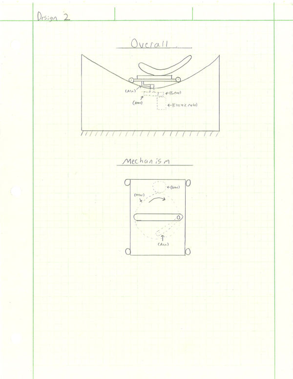
Concept Design 2
The second design is a floor base concept that will rock with the same motion as a swing. The seat will also rotate to allow for swinging in both directions. It will be controlled by a variable electric motor that drives a cam.
Concept Design 3
The third design is a floor base concept that will rock with the opposite motion as a swing. The seat will also rotate to allow for swinging in both directions. It will be controlled by a variable electric motor that drives a cam. The cam will cause an arm to pivot back and forth.
Selected Concept Design
Based on the above decision matrix, we have chosen design 1 to be our final candidate. This design rated so highly due to several features. The first is its strong frame design that will ensure the design does not tip over. The second feature is the spring in the mechanism that will allow the swing to stop if a child were in the way. This swing will be mobile on casters, however it is a somewhat bulky structure that could be cumbersome to push. Overall, this is a feasible design for engineering students to build and it meets the family’s request to have a larger, stronger “baby” swing.
Decision Matrix
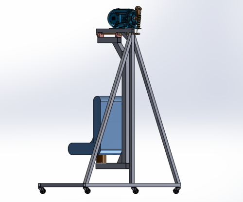
Overview of Selected Design
This section will describe a detailed design process
We started our design process by meeting with the family and therapist. We discussed what needs our mechanism needed to meet. They had a swing for the child already, but she is quickly growing out of it. She also would kick, and work herself out of the current seat.
The family essentially wants a larger swing and that is what we have decided to provide to them. They also have a specific seat they want us to use. This new seat is specifically for special needs children and has restraints already built into the seat. It also has a detachable base so later on the seat can be switched out for a larger seat as she grows.
Our design will have a sturdy base that will have casters at all four corner that lock so it can not only be moved easily but also secured in place. The arm of the swing will be in the shape of a C to encompass the seat and keep the moment arm close to the action of the mechanism. This will add stability to the mechanism by centering most of the weight over the support beam.
The support beam will be securely fastened to the base and have supports from both sides and across the base to give it four points of contact to the base. The whole structure will be made from aluminum tubing for not only its strength, but its weight savings over steel.
Describe Design Details
Base – The base will be made of 1.25” 6061 Aluminum square tubing with a 1/8” wall thickness. It will be 48” long and 24” wide to fit through most standard door ways. At each corner will be a caster with a solid rubber wheel to allow both mobility and dampening from the swinging motion.
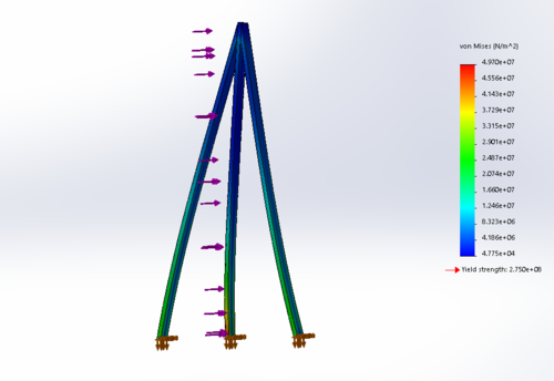
The support beam or the “back” – This will be what connects the base of the swing to the swing arm itself. It will also have the motor mechanism attaches to it. It will also be made out of aluminum square tubing. It will be attached at the bottom of the beam to the base as well as three support beams coming from across the base and opposing sides.
Mechanism – The mechanism on the swing will allow for a gentle and adjustable speed swinging motion. The motor will drive a cam that will work a spring attached to the swing arm. This will allow for a gentle start up and a safe motion as the motor will not be directly driving the swing. The swing will move form the input of the spring and can be swung manually with the power off if wanted.
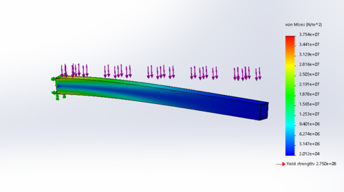
Swing arm – The swing arm will be int the shape of a C to wrap around the seat. Each corner will have a support to help fight deflection of the aluminum. There will be ample room between the swing arm and the sides and the top of the seat to allow for plenty of headroom for the child for a safe experience.
Seat and Base – Both the swing and the base have been provided to us by the family. The seat already has built in restraints to safely strap the child in. It also has a detachable base to allow for a newer larger seat, to accommodate the child as she grows. The base will be attached to a plate on the swing arm to add rigidity to the base of the seat and also allow it to rotate and provide both swinging motions as described earlier.
Engineering Analysis 1
Stress analysis of the back support section
Engineering Analysis 2
Stress analysis of the top bar
Engineering Analysis 3
Stress analysis of the swinging bar
CAD Drawings
Bill of Materials
Document Fabrication Process
Sydney Bogard working the frame through a manual tube bender to obtain our desired radius.
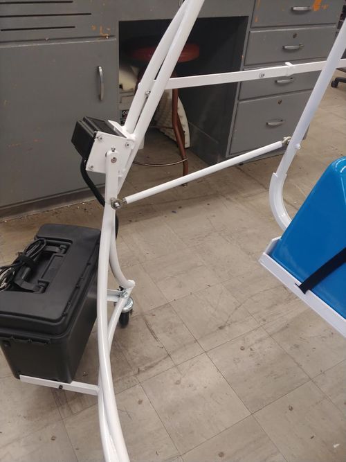
Shown is our first frame assembly. We were able to determine that added supports at the base of the frame were needed to reduce resonance.
Jeff Randolph assists the team in welding on supports to our frame.
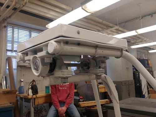
Here, we have added the extra supports and attached the swing arm.
Testing Results
Alissa McDougle tests the strength of the frame with a static load force test.
Once the swing arm and base plate are installed, a dynamic load is applied for strength testing.
Carson Hampton powder coating our completed frame after verifying its strength and reliability.
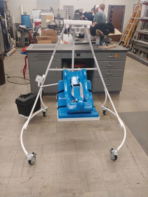
Completed Design Photos
Instructions for Safe Use
Do not use the device unless supervised by an adult that has been fully understood the safe use of this product.
Keep fingers away from moving mechanism.
Wrap power cord to avoid tripping hazzard.
Do not collapse swing with a child inside.
Ensure the seat is in a locked position before operating the product.
Ensure all bolts are tight before operating the product.


