Spring 2021 Project 09b: Rowing Bike Novel Gear Mechanism
Abstract
Group 9B is partnering with Melissa Draper for the Early Intervention and Mechanical Engineering Spring 2021 project to design a rowing bike for middle and high school aged kids with disabilities. Existing models from previous semesters are available for examination and have helped establish our initial concept candidates. Feedback has been given from Leanne Turpin, who has worked with the previous semester’s project, regarding problems the current design faces.
Craig Rackley, Aaron Lawson, Brandon Reynolds, and Alex Ogle (clockwise from top left)
Problem Statement
To design a bike that would be able to be driven by a rowing push and pull motion on the handlebars only. This pushing and pulling motion must create a reasonable amount of speed output so the rider will enjoy the ride and want to continue to ride the bike. However, the bike still needs to be easy to use and safe while also requiring some effort from the rider to create a form of exercise. This bike can have no input or motion of the feet or lower body. Riders are around teenage years so must be gender neutral with design (colors, decals, words, etc.).
Design Specifications
The bike is intended to have only linear motion in operation. The bike design should be balanced where it requires no user input to stay upright. The design must keep the user’s feet free with access to touching the ground. The input mechanism for the drive train cannot include a ratchet system. Any input from the user has to turn the drive train and cause movement. The bike is intended solely for indoor and possibly sidewalk usage. The target users for this bike range from middle to high school students so the bike needs to be sized accordingly.
Background Research
There are already some elliptical type bikes on the market. These types of bikes vary on design but typically require the user to be standing with both feet on the bike to operate. Most also rely on input from the lower body to operate. For designing the input of the bike mechanisms such as a handrail cart and rocking powered scooter were looked at for inspiration.
Concept Design 1
Create gear box that would allow two different directions of input and produce one direction of output. This works using a “slider” gear that would pivot back and forth.
Concept Design 2
Fix pivot of rowing arm. Attach gear to each side. Attach gear and one-way clutch to each side of chainring pivot. Use idler gear on one side of mechanism to flip rotation. One-way clutches allow power to be transmitted both by pushing and pulling on rowing arm. No set stroke length. Smoother operation than concept 1. Heavy and untested.
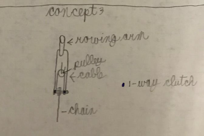
Concept Design 3
Borrowed from Rockboard scooter. Same mechanics as concept 2. Cables instead of gears. No set stroke length. Smoother operation than concept 1. Lighter than concept 2. Already proven to work.
Selected Concept Design
We selected of first Concept design, we believed that this would be the easiest design to create and would work the best.
Overview of Selected Design
The design used allows both forward and backward rowing inputs to propel the bike forward.
Engineering Analysis 1
The goal of this analysis is to determine the angle of twist of the steering column under certain conditions.
Engineering Analysis 2
The goal of this analysis is to determine the gear reduction of the drivetrain.
Engineering Analysis 3
The goal of this analysis is to determine the theoretical maximum speed of the bike.
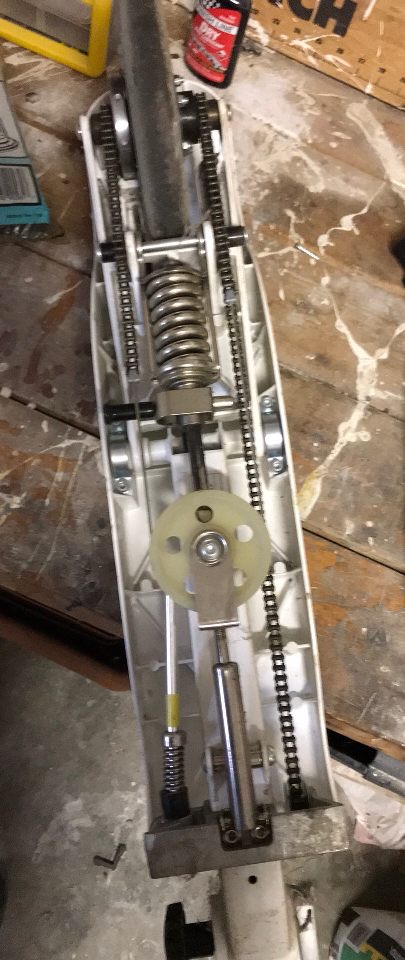
To start out we cut out the previous mechanism that was on the bike. We then designed our gear box using SolidWorks and and 3D printed it before finally using the CNC to machine it out of aluminum. After we received all of our ordered parts we assembled the gear box and installed it onto the bikes existing drivetrain. To mount the gear box we bolted it to the the frame by drilling a hole through the body and we also welded a metal rod underneath it to support it from the bottom. Once the gear box was finished we used two steel plates and created press fit holes for bearings. These plates were welded to the frame in front of the gear box. This was our mounting point for our pivot arm. After we finished welding, we assembled the pivot arm. To help restrain the arm from interfering with the gear box, we installed a limiter to limit the arms rang of motion.
Note: Not noted above ~we drilled and tapped holes in 2 of our 2.5 in gears and 1 in our pivot armD D
Testing Results
We rode the bike up and down the hall multiple times as well as propped it up and ran it to make sure there was no sticking or locking up.
Completed Design Photos
Instructions for Safe Use
To safely use the the bike a person needs to sit in the seat and fasten the seatbelt. Then place their feet on the pedals and row the bike back and forth.


