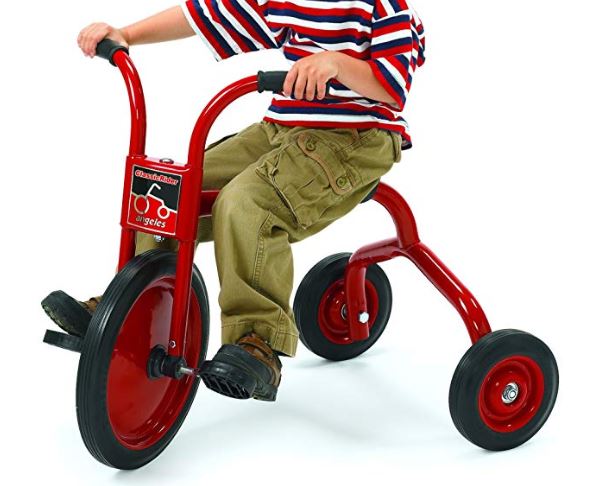
A child with Caudal Regression Syndrome is in need of a therapeutic tricycle to help improve knee flexion.
From Left: Braeden Shelton, Cameron Brakebill, Morgan Ivey, Luke Fleming, and Glenn Hammons
Problem Statement
A child with Caudal Regression Syndrome is in need of a tricycle for mobility as well as therapy. The parents and coordinator of our child would like a bike to not only help with the child’s therapeutic needs but also to be able to get her out and moving freely on her own. Our goal is to help improve the child’s knee flexion while giving her the bicycle riding experience.
Design Specifications
1. The Trike needs to support our child’s weight.
2. The Trike needs to be adaptable and able to grow with child.
3. The Trike needs to withstand the forces she can currently exert as well as the in the future as she grows stronger and more capable.
4. The Trike needs to be easily operable for a small child.
5. The Trike needs to help the child progressively increase mobility in her knees.
6. The Trike needs to be fun to ride.
Background Research
We Researched our basic Designs to see if they were already designed, or for sale. This is what we found
1. Electric/Motorized Tricycle – More faster moving parts that can fail. Battery Powered.
Electric/Motorized Tricycles are for older kids, or drift bikes. They all seem electrically powered, not aided. Could be modified to fit the needs of the child.
2. Traditional Hand Cranked Bike – Hard to steer. Simplest to design / build.
Traditional Hand Crank Bike is what the therapist, and mother both considered. However, this would be hard to steer. We would have to make the pedals, seat, and handles adjustable.
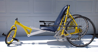
3. Lever Powered Recumbent Bike “Catapult” – Extremely customized. Lacks pedal to create bending in the knees. For adults only.
The Lever Powered Recumbent Bike is not for sale. It was made by Tom Robbins. They also lack pedals, which are essential for this project.
Concept Design 1
A standard Hand Crank tricycle design with adjustability to accommodate for growth and changing therapeutic needs
Adjustable pedals to aid in knee flexion improvement.
Hand crank to drive front or rear
Using motion from the rear axle to passively drive feet using adjustable pedals to accommodate for changes in knee mobility
The Basic Frame is not a new concept, would allow for more time to be spent on incorporating passive knee flexion for child.
Concept Design 2
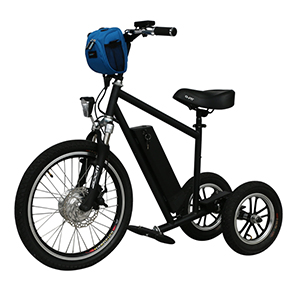
A Standard Tricycle design utilizing a hub motor for assisted pedaling and traversing rough terrain
Full Electric Trike
Front Wheel Drive
Limited options to incorporate knee flexion while driving bike.
Could use torque sensors to determine correct amount of pedal assist
Motor Can be laced into any size wheel over 12in in diameter. Also using a standard sized fork allows for much more adaptability than a custom build
A 36v System with a small 6AH Battery would provide 216 Watt-Hours of Power.
Allows for use of V-Brakes for simplicity
Allows for a simplified frame design
Concept Design 3
A Drift trike style tricycle utilizing a Mid Drive motor on the rear axle for assisted pedaling as well as increase torque over a hub motor.
Utilizing a standard trike frame along with a Mid-Drive Electric motor kit to drive the bike as well as introduce knee flexion easily
Would allow for more power for driving off road
gives many more options for passive drive of knees
seating position is non-typical of a standard tricycle
Ability to use a Disc Brake for Increased stopping power over v-Brakes
A 36v System with a small 6AH Battery would provide 216 Watt-Hours of Power.
Utilizing a hand crank to get our child active and moving, but also with the added benefit of the hub motor for traversing rough terrain and climbing hills.
The heaviest of all designs but would incorporate the electric assist with the hand crank to allow for easier driving
Decision Matrix
Overview of Selected Design
The design we have chosen will incorporate 2 electric motors. The Main of which will be used to drive the trike, and the secondary one which will operate the therapeutic aspect of the project. The Design will center around a pre-existing trike model that we plan to heavily modify to suit the needs of the child.
Describe Design Details
The Trike will be a modified version of a pre-existing trike that is common to pre-schools and therapy centers. The front end will have the existing crank set removed and be modified to fit an electric motor. We plan to make the seat adjustable forwards and backwards to accommodate for the child’s growth over time. We intend to meet the therapeutic needs of the child by incorporating a separate crank set farther back on the trike that will be driven by an electric motor. This crank set will allow the child’s legs to be slowly driven in a way that overtime should help to increase knee flexion. The battery as well as controllers for both motors will be located in a dual purpose basket on the rear of the trike. This will allows to waterproof all the critical components and connections as well as providing a convenient carry basket for the child.
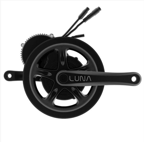
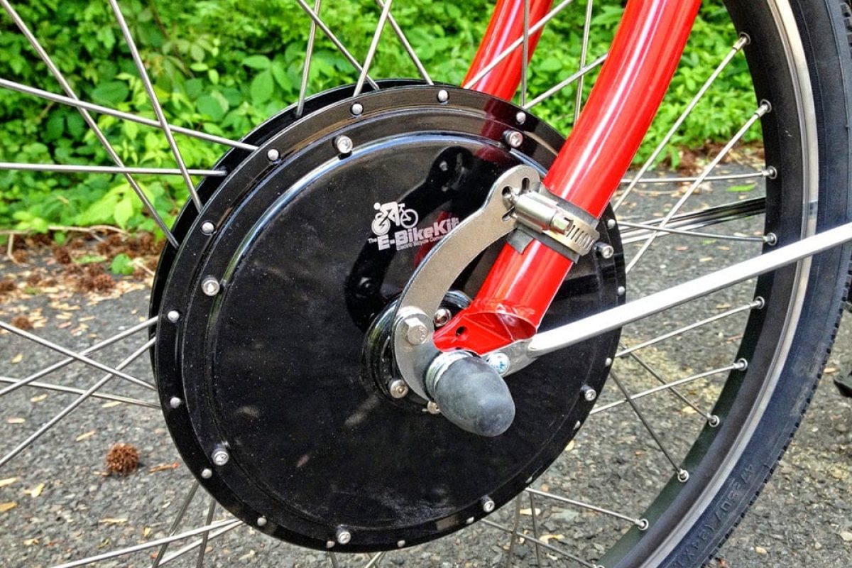
Hub Motor
The main powerhouse of the trike will be a 500-750W electric hub motor, with integrated controller, mounted in place of the standard front wheel. The standard forks will have to be Modified to accommodate the height as well as the new width of the Hub Motor.
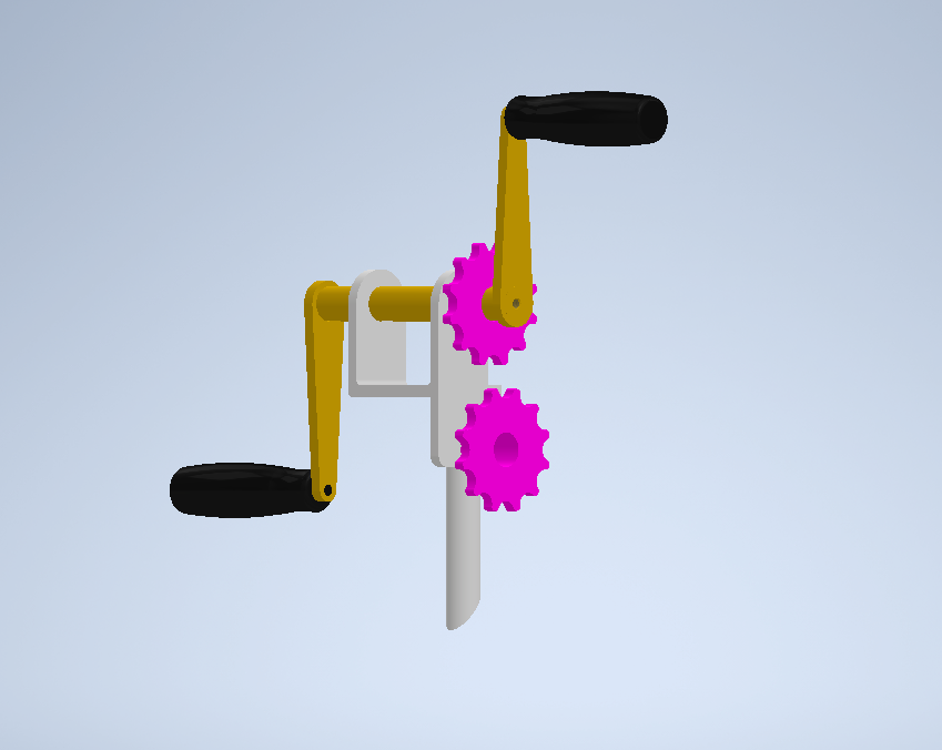
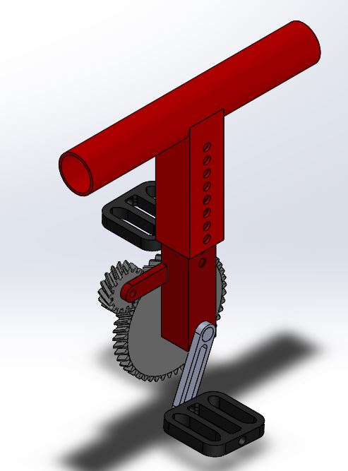
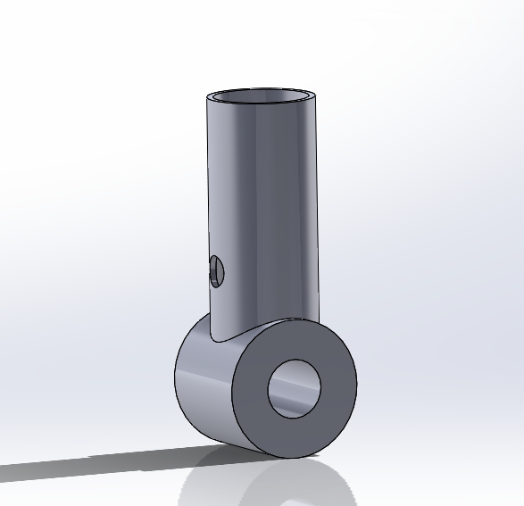
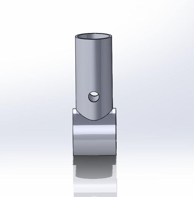
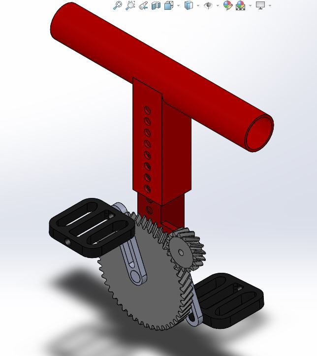
Electric Crank Set
To assist in increasing knee flexion of our child the trike will feature a crank set that is driven by a small electric motor. The crank set will have adjustable pedal lengths to accommodate for changes in our child’s knee flexion.
The motor will more than likely be a small rc- style electric motor that is current limited to avoid over driving the child’s knees. It will be mounted directly above the crank set and transmit power through a 3 to 1 gear set of 3d-Printed Helical Nylon gears.
Basket
The basket on the rear of the trike will be designed in a way that hides its true function as a waterproof electronics box and instead appears to be a standard bicycle mounted basket.
The controller for the Hub motor will be mounted in a way as to still provide access to make the necessary adjustments to power output and speed as the child grows stronger and more able.
Engineering Analysis 1
Here we calculated the force required for the bike to go up a 20 Degree hill, while in grass. We got the coeffecient of grass from an study done in New Zealand (see reference below). We also created an exel spreadsheet to find to required torque needed to get up this hill without accelerating, with diameter increasing by 1 inch. We could not find any max torque specs for the motor, but we have concluded that since the hub motor we are wanting to use is made to work with the weight of full sized adults, we are assuming that we will have plenty of torque with a 750W motor for her to get around.
Engineering Analysis 2
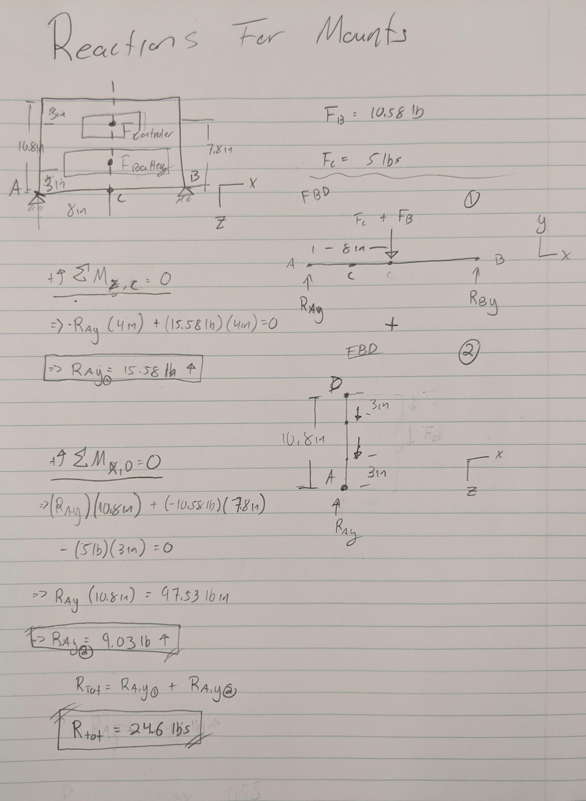
Here we are calculating the required force needed for mounting brackets. We are puttng a basket on the back of the bike to put the battery, hub motar controler, a mirco controler, and some buck converter. The mirco controler and the buck converter’s weight we are assuming is neglegable compared to the weight of the battery and the hub motar controlar. We are also assuming that the weight of the basket itself is neglegable. Due to the symetry of the static systm, reaction at point B is going to aid in supporting the loads.
Our finding concludes that the total reaction forces is 24.6lbs. The selection / design of mounting brackets will be based off this calculation. Very likely we will weld the basket to the bike frame instead of mounting it.
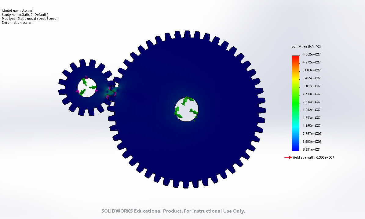
Engineering Analysis 3
This is a Stress analysis of the gears that will turn the petals with a motor which provides 2.2 lbft of torque. From this analysis we have a factor of safety of 13.215.


