Spring 2026 Project 11: Mount for Speech Device

Abstract

This project involves the design of a rigid, headrest-mounted tablet holder for a child who uses an eye-tracking speech-generating device for communication. Because the device relies on precise eye movement detection, the mount must prevent all unwanted motion during vehicle travel. In collaboration with a licensed therapist, the design prioritizes stability, safety, proper positioning, and ease of use. The final solution provides a secure and reliable mounting system that supports consistent communication and improves accessibility during transportation.
Gabe Simpkins, Camden Latham, Kale Davis, Drew Hillyer, Michael Langham, Hanna Loretz

Problem Statement

The challenge of this project is to design a rigid, safe, and adjustable headrest-mounted tablet system that eliminates device motion and supports accurate eye-tracking communication in a moving vehicle.

Design Specifications

  • The mount must swivel in all directions
  • The mount cannot stick out more than a few inches
  • The device must easily attach and detach
  • The mount must fit in multiple vehicles and be easily removable
  • The mount must be very rigid

Background Research

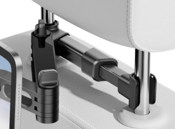
For this project, we conducted background research on existing methods used to mount a speech generating device to vehicle headrests. Our goal was to find mounting systems that could securely support an eye-tracking speech device during vehicle motion, particularly under bumpy driving conditions. We examined a range of commercially available headrest mounts and support brackets. Many of these designs relied primarily on plastic components and were intended for lightweight devices such as tablets. However, the speech device used in this application weighs approximately 10 pounds and must remain stable and precisely positioned for accurate eye-tracking functionality. This weight requirement, combined with the dynamic forces experienced during vehicle movement, indicated that a stronger material like metal would be necessary to ensure structural integrity and safety.

Concept Design 1

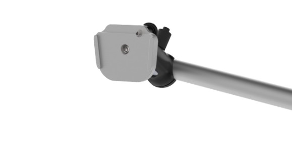
Concept Design where we incorporate a premade device mount and attach it a bracket with holes through its center. U-bolts would be used to attach the bracket to the headrest through predrilled holes.

Concept Design 2

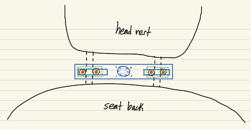
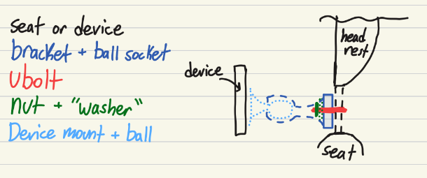
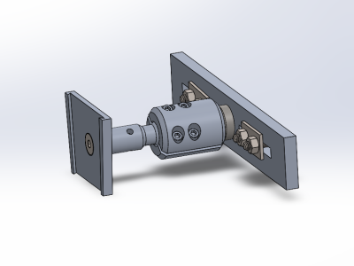
Concept Design using custom made device mount that attaches to a lockable ball joint that is connected to a slotted bracket mounted to the seat using U-bolts.


Concept Design 3

Concept Design where a ball jointed device mount attaches to a main body that is clamped in between the headrest posts.

Selected Concept Design

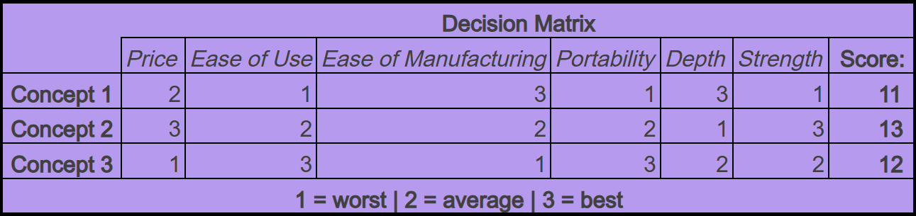
To evaluate our designs we incorporated an unweighted decision matrix. We scored each concept from 1 (worst) to 3 (best) across six key requirements. Our group believes every requirement carries equal weight in this project, so we used an unweighted matrix to determine the best overall design.

Decision Matrix

Overview of Selected Design

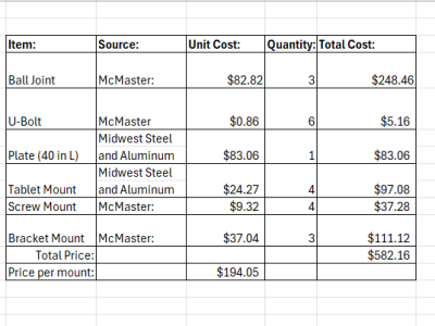
We have formally selected Concept Design Two as it represents the most robust and thoroughly engineered solution among our three candidates. This design secured the highest overall score in our decision matrix (above), specifically earning top marks of three for both cost-efficiency and structural integrity. Our high rating for price stems from an estimated production cost of approximately $300 for three units, a figure we anticipate Designs One and Three would exceed. Furthermore, Design Two demonstrated superior structural strength when compared to the alternative configurations. While the design received a low score for depth due to its significant protrusion from the headrest, we have determined this is a manageable trade-off since the extra depth will not impede the device’s overall functionality.

Describe Design Details

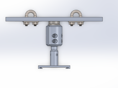
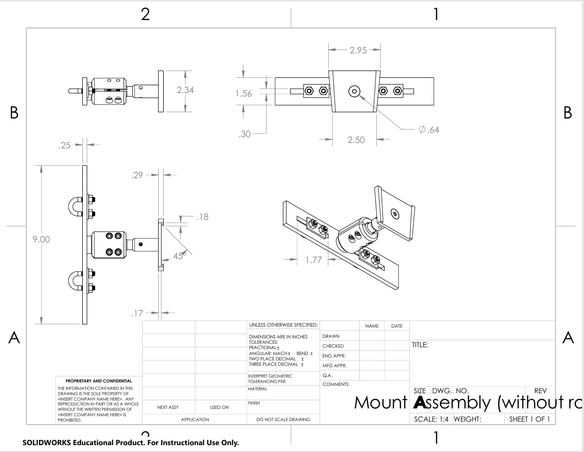
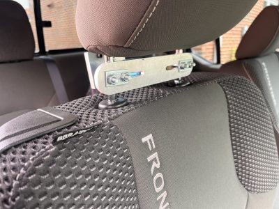
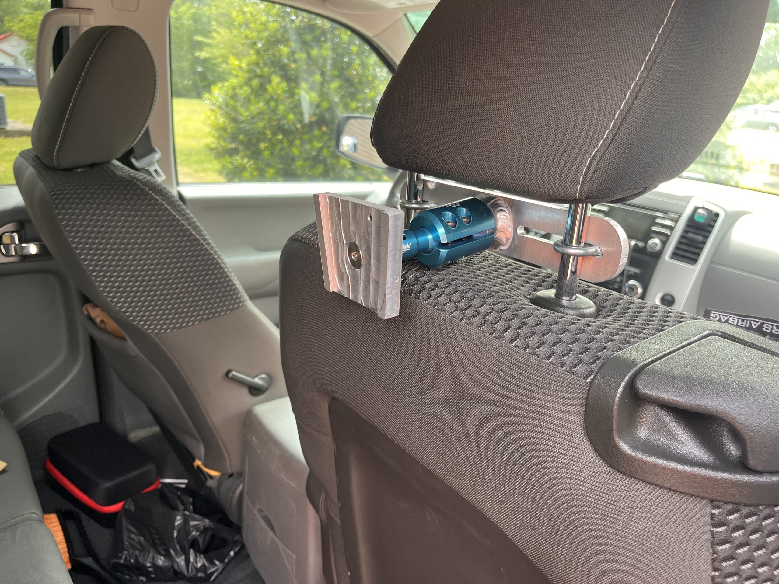
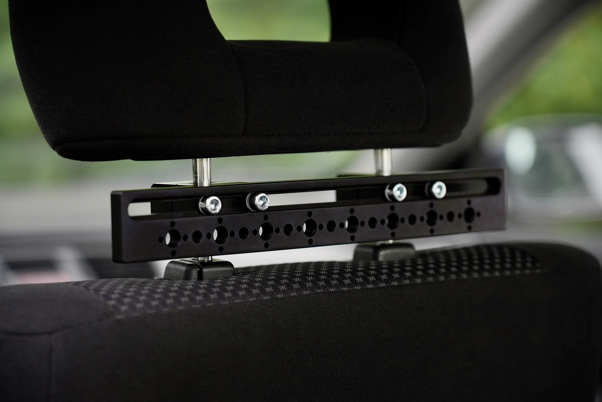
This design features universal compatibility, allowing for secure mounting across various vehicle models. Utilizing U-bolts provides a high-strength, rigid connection to the head rest while remaining easily detachable. To accommodate varying headrest dimensions, the bracket incorporates a slot where the U-bolts can slide closer or further apart. Optimal device positioning is achieved via an integrated swivel joint, which can be tightened to keep a desired position. The mount maintains a secure grip on the device during use while facilitating quick removal when necessary.

Engineering Analysis 1

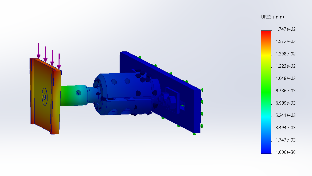
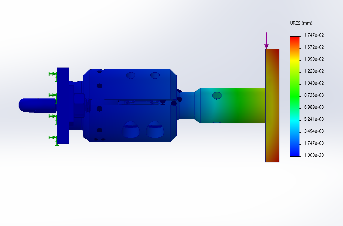
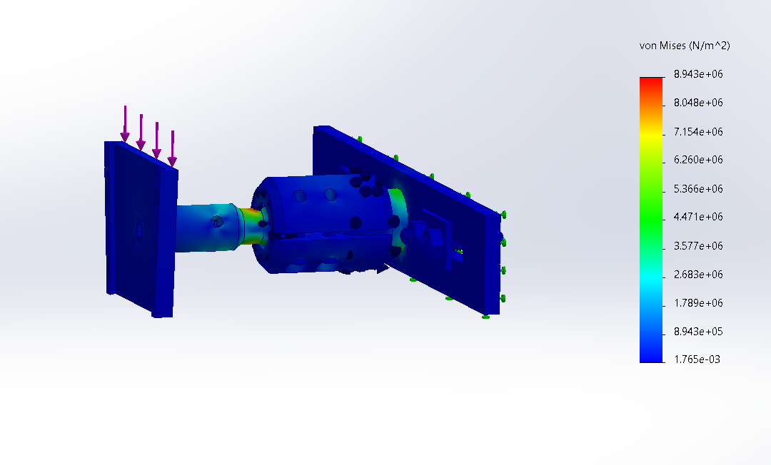
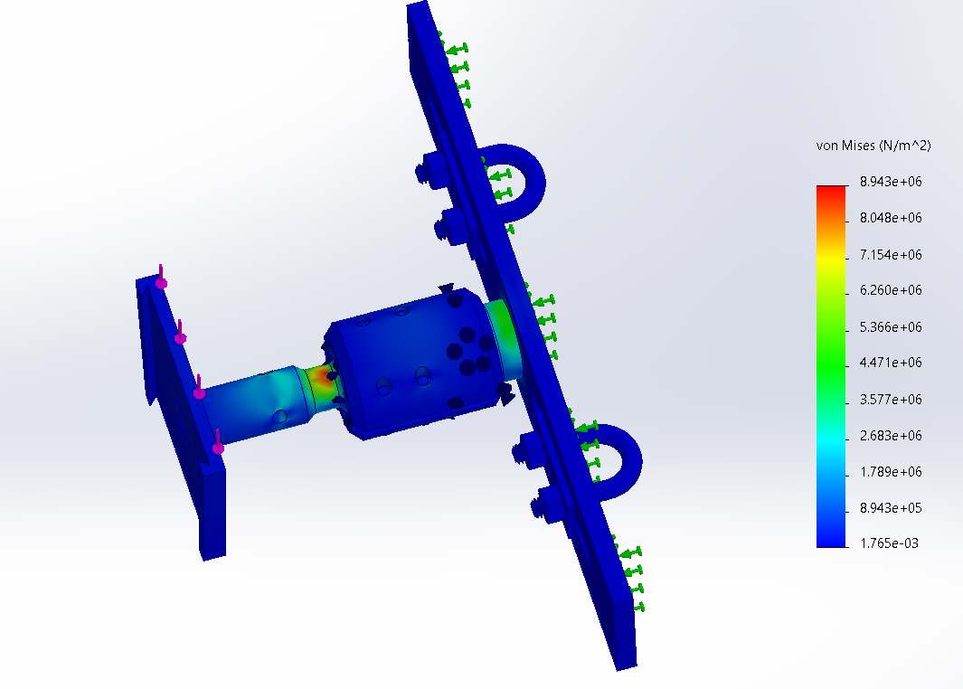
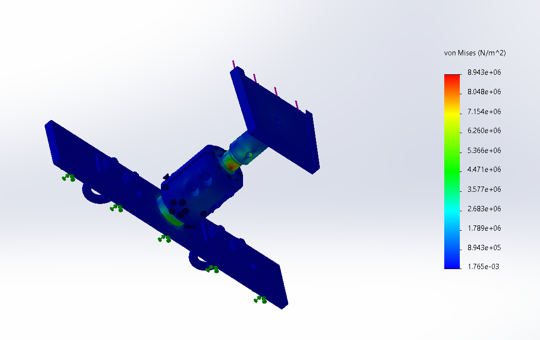
To evaluate the stiffness and stability of the car mount, a displacement analysis was performed using SOLIDWORKS Simulation. A load of 10 pounds was applied to the end of the mount to represent approximately twice the weight of the eye gaze speech-generating device. This increased load was used to create a safety factor, ensuring the mount would remain stable even under forces greater than normal operating conditions.

The simulation measured how much the mount would bend or deflect under this load. Results showed a maximum displacement of 1.747 × 10⁻² mm, which is extremely small. This indicates that the mount design is very rigid and capable of supporting the device without significant movement.

Overall, the displacement analysis demonstrates that the mount maintains structural stability under loads well above the expected device weight, helping ensure reliable and safe operation during use.

Engineering Analysis 3

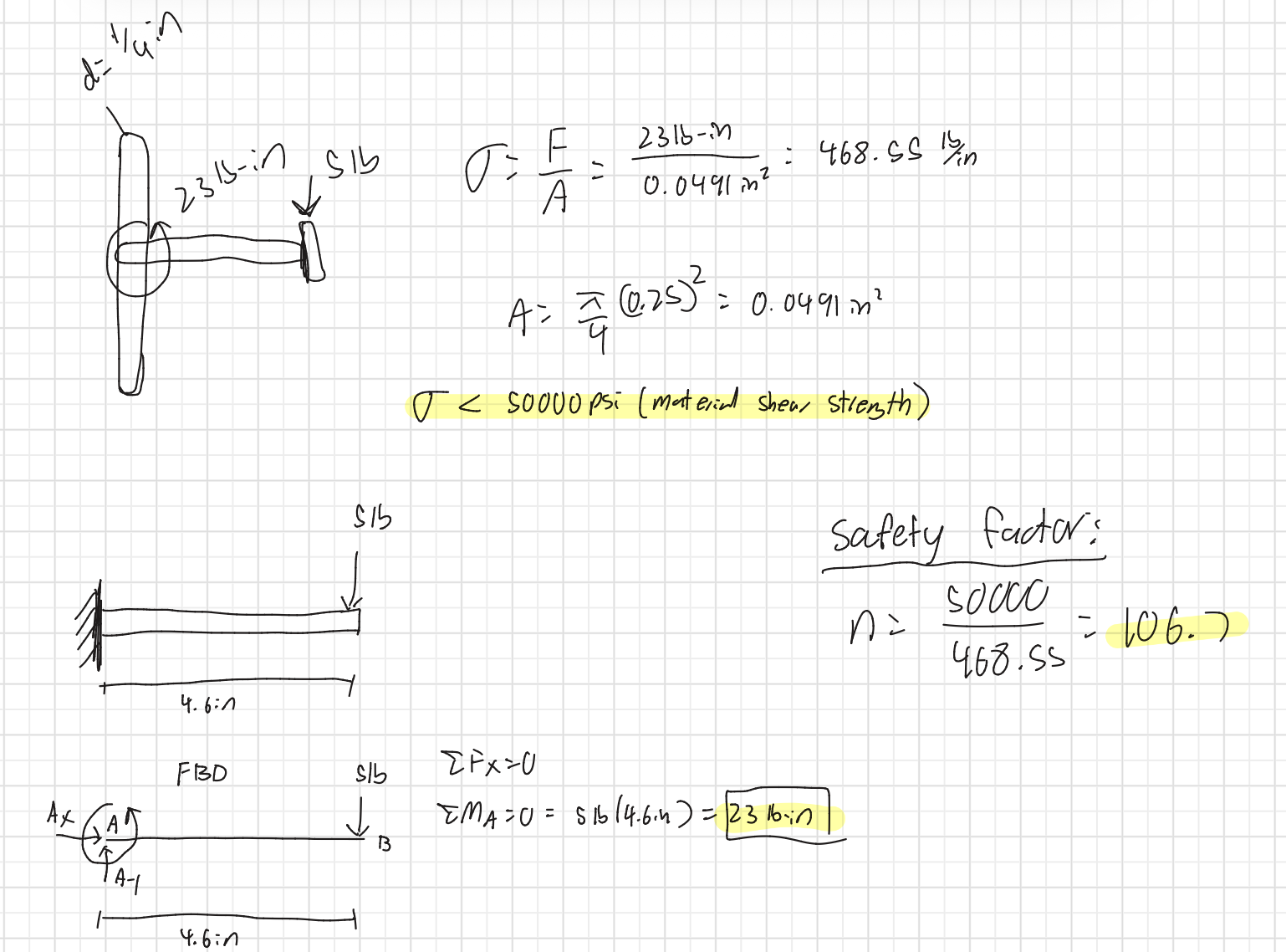
In addition to the computer simulations, a simplified analytical calculation was performed to estimate the safety factor of the mount. This hand calculation modeled the arm of the mount as a cantilever beam with a load applied at the end, representing the weight of the speech-generating device.

A 5-lb load was applied at a distance of 4.6 inches from the mounting point, resulting in a calculated bending moment of 23 lb·in at the base of the arm. The cross-section of the arm was approximated as a circular member with a diameter of 0.25 inches, giving a cross-sectional area of approximately 0.0491 in².

Using stress is equal to force over area, the calculated stress in the member was approximately 468.55 psi. This value was then compared to the estimated material shear strength of 50,000 psi. Based on this comparison, the simplified calculation produced an estimated factor of safety of approximately 106.

CAD Drawings

Bill of Materials

Document Fabrication Process

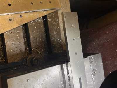
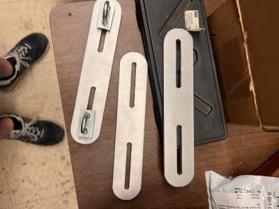
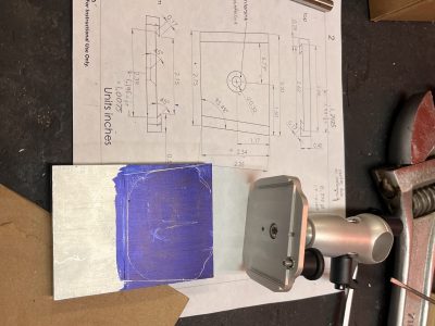
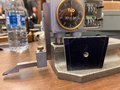
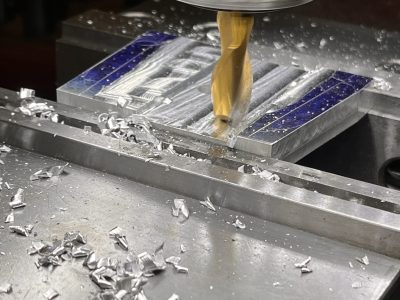
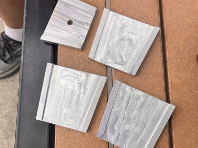
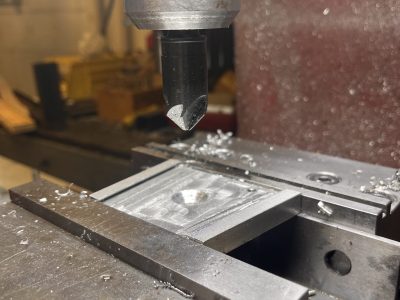
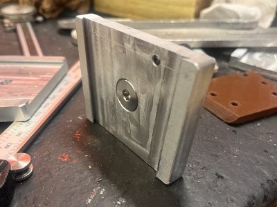
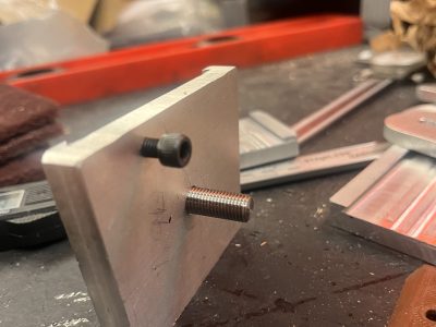
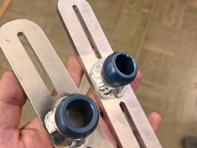
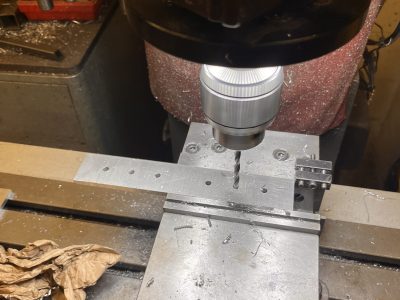
We began by taking measurements and creating sketches. Next, we cut the seat post bracket to its finished length and began milling the slots for the U-bolts. We then chamfered the edges using a bench sander. Moving on to the device mount, we traced the angles from the provided mount using layout dye and a scriber. After that, we milled the angles down on both sides. Treating this new angle as the horizontal plane, we milled a 45-degree angle and removed the material between the two sides. We then centered the hole for the through-bolt and countersunk it using a 45-degree bit. Following this, we drilled and tapped a hole for a thumbscrew to lock the device in place. To connect the mount to the seat post bracket, we cut the ball joint in half and TIG welded it to the bracket. To assemble the entire unit, we placed each ball into its respective socket and tightened the assembly using an Allen wrench. 

Testing Results

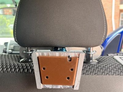
The mounting system was tested in several stages to verify fitment, functionality, and stability. The aluminum mounting bracket was first tested on vehicle seat headrest posts to ensure the slotted holes provided enough adjustment range to accommodate different vehicle seat configurations. The tablet mounting bracket was then evaluated by 3D printing the receiving end of the tablet interface to confirm the 45-degree angle and overall fitment dimensions before final assembly, since the actual tablet was not available during development. Finally, the complete assembly was installed on the back of a vehicle seat with the tablet mounted in place. Testing included simulated step inputs and general movement to evaluate mount stability, rigidity, and vibration response, as well as verification of the adjustment range and positioning capability of the ball joint assembly.

Completed Design Photos

Instructions for Safe Use

There are a few important safety instructions and basic guidelines to ensure safety that are listed below:

  • Mount is designed to securely hold the eye-tracking speech device on the vehicle headrest.
  • Before driving, ensure the mount, ball joint, and tablet bracket are securely tightened.
  • Fully slide the device into the bracket and hand-tighten the retaining bolt before use.
  • Carefully support the device when making adjustments and re-tighten all hardware afterward.
  • Regularly inspect the mount for loose hardware, cracks, or other damage.
  • Do not use the mount if any component appears damaged or loose.
  • The mount is not crash-rated; always ensure the device is properly secured during vehicle operation.

  • To ensure safety only use for intended purposes, mount is safe up to 30 lbs.

Project Summary/Reflection

Overall, the project was a success. We designed the mount in CAD, ran tests to ensure it was strong enough, and machined with a mill. The mount was designed to be sturdy, adjustable, and sit at the right distance from the child’s eyes. Of the criteria, the mount was able to meet all of them with a sturdy design, ball joint that can lock in place, and adjustable U-bolts that can fit onto most vehicles. The mount also helped us in our CAD design, machining, and welding skills, but most of all, it taught us that we can have a positive impact on our community.

Semester

2026 Spring